STROBO is a xenon strobe light (stroboscopic light) that can flash automatically or it can be controlled by a PC, by other lights or by a microphone. Please note that the components are grid power supplied (230Vac), hence do not touch them! Please also consider that the xenon lamp is powered by a 600Vdc voltage (at A, K pins) and the trigger voltage (lamp pin 1) is more than 4KV!

Xenon strobe light schematic
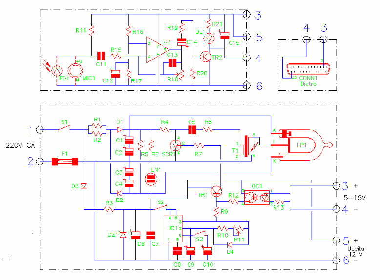
I/O:
- 1, 2 - power input (220-230Vac), please note that components are not insulated, please do not touch them
- 3,4 - input to trigger a flash (opto insulated, 5-15Vdc)
- 5, 6 - low power output (12Vdc)
- S1 - main switch)
- S2 - internal oscillator ON (enables auto flash)
- S3 - internal oscillator frequency scale
- R11 - internal oscillator frequency selection
Auxiliary module 1: it allows to trigger a flash when another flash or sound is detected.
Auxiliary module 2: it allows to connect the xenon strobe light to a parallel PC port to trigger flashes.
Components list, resistors:

- R1 - 1 KOHM 17 W (it must dissipate heat)
- R2 - 1 KOHM 17 W (it must dissipate heat)
- R3 - 5600 OHM 5 W (it must dissipate heat)
- R4 - 27 KOHM 1/2 W
- R5 - 1 MOHM 1/2 W
- R6 - 270 KOHM 1/2 W
- R7 - 330 OHM 1/4 W
- R8 - 100 OHM 1/2 W
- R9 - 1 KOHM 1/4 W
- R10 - 680 OHM 1/4 W
- R11 - 10 KOHM logarithmic potentiometer
- R12 - 1 KOHM 1/4 W
- R13 - 470 OHM 1/4 W
Components list, capacitors:
- C1 - 22 uF 350 V or more, electrolytic
- C2 - 22 uF 350 V or more, electrolytic
- C3 - 22 uF 350 V or more, electrolytic
- C4 - 22 uF 350 V or more, electrolytic
- C1, C2, C3, C4, choose capacitors with high discharge current
- C5 - 100 nF 630 V polyester
- C6 - 470 uF 25 V electrolytic
- C7 - 100 nF polyester
- C8 - 10 nF polyester
- C9 - 47 uF 25 V electrolytic
- C10 - 470 uF 25 V electrolytic
Components list, other:
- IC1 - NE.555
- TR1 - BC.237
- SCR1 - TYN.612
- OC1 - 4N.25
- D1 - 1N.4007
- D2 - 1N.4007
- D3 - 1N.4007
- D4 - germanium diode
- DZ1 - zener diode 12 V 1 W
- S1 - switch (main power switch)
- S2 - switch
- S3 - switch
- T1 - xenon trigger transformer
- F1 - fuse 250 V 1/2 A
- LN1 - neon lamp without resistor
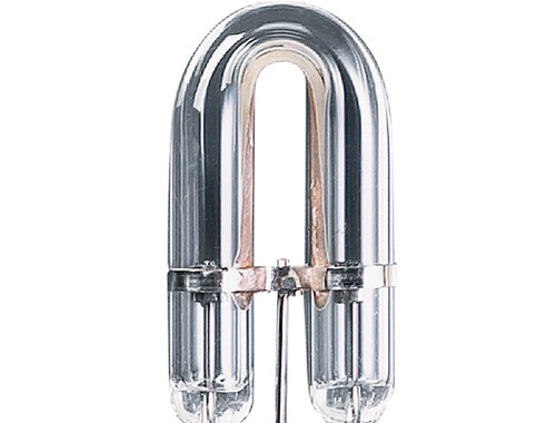
- LP1 - xenon strobe tube
Auxiliary modules components, resistors:
- R14 - 4700 OHM 1/4 W
- R15 - 1 KOHM 1/4 W
- R16 - 10 KOHM 1/4 W
- R17 - 10 KOHM 1/4 W
- R18 - 470 KOHM trimmer
- R19 - 470 OHM 1/4 W
- R20 - 100 KOHM 1/4 W
- R21 - 820 OHM 1/4 W
Auxiliary modules components, capacitors:

- C11 - 100 nF polyester
- C12 - 10 uF 25 V electrolytic
- C13 - 220 pF ceramic
- C14 - 2,2 uF 25 V electrolytic
- C15 - 100 uF 25 V electrolytic
Auxiliary modules components, other:
- IC2 - uA.741
- MIC1 - pre-amplified electret microphone
- FD1 - photodiode BPW.34
- DL1 - led diode
- TR2 - BC.237
- CONN1 - D connector, 25 poles male (for LPT PC port)
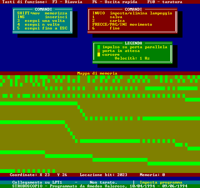
Xenon strobe light PC controller
The original xenon strobe light PC software has been developed in QuickBasic for DOS. It is possible to set a memory array to trigger flashes. Of course you can write your own software, in a modern programming language... simply give 5V to pin 3, 4 of the stroboscopic light.
Project started on: Jan, 1994. Status: just for personal use.