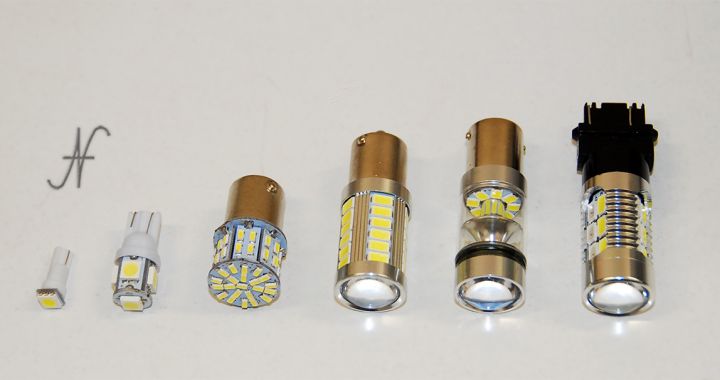
It will have happened to anyone to buy LED bulbs for their car, but also for their home, and to see them broken, turned off, after a few hours of operation. In this article I will briefly analyze the causes of the breakage and suggest solutions.

But why don't LED bulbs last the promised 10000-30000 hours?
I really tried several LED bulbs and I realized that, if the bulbs do not last long, the main problem is a incorrect design of the same. It seems strange, but that's exactly how it is. It is not a question of materials, especially if we are talking about low-power bulbs: position lights, LED indicators, button backlight lamps. It's really a question of design, so much so that by correcting errors where possible, these light bulbs could work forever!
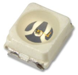
For those who have time and desire to study a datasheet (technical sheet) of an LED, you can follow this link. It is just an example of a high-brightness white LED, taken at random among those that can also be used in LED lamps for position lights, reversing lights and also for the backlighting of dashboards.
Operating parameters of the LEDs
The parameters to be taken into account are as follows:

- Forward voltage (VF): indicates the voltage that develops at the ends of the LED when it is crossed by current. In the datasheet you can see that it is between 3.7V and 4.2V.
- Forward current (IF): the current that the LED must travel to turn it on. The datasheet suggests a current of 20mA, which must never exceed 30mA.
- Junction temperature (Tj): the maximum internal operating temperature (maximum junction temperature), which must never be higher than +110°C in our example LED.
- Thermal resistance Junction/Ambient (Rthja): the dissipation factor, how many degrees the junction temperature increases compared to the surrounding environment for each Watt of power absorbed (and therefore dissipated). In our example LED, 400K/W = 400°C/W.
Now, if I were to advise the designer of an LED lamp on how to design it, I would certainly start from the data listed above (obviously after having defined that the type of LED taken into consideration is suitable for the application in terms of color and brightness).
Calculation of thermal dissipation
So, having determined that our sample LED can be fine, we must adjust the current so that the heat dissipation is correct.
If traveled by the recommended current of 20mA (= 0.02A), our LED will have a voltage drop of about 3.7V.
Therefore the power dissipated is:
Watts = Volts * Amps = 3.7 * 0.02 = 0.074W
At this power, the temperature of the led junction (the internal temperature of the led) will increase by:
T = Watt * Rthja = 0.074 * 400 = 29.6°C
What did we discover? That if we use the values suggested by the LED manufacturer, the LED will increase its internal temperature by almost 30°C compared to the temperature of its environment (the dashboard box, or the inside of the car headlight), provided that the mounting technique suggested in the datasheet is used.

Since the maximum junction temperature (Tj) is 110°C, this means that our LED must never work inside a headlight or dashboard when the temperature of the latter is higher than 80°C, which for our application is perfect.
Unfortunately, designers may decide to increase the operating current of the LED (IF), in order to make it brighter. Or they could choose a less performing LED and increase the operating current (IF) in addition to the maximum value, making the LED heat up disproportionately and reducing its life in a sensitive way.
Or they may choose a current regulator that is too delicate. The current regulator is used to impose the operating current (IF) on the LED, but, if the regulator is poorly designed (even for the components of the regulator there are datasheets and calculations must be made!), it could be damaged before the LED itself. In case the current regulator is damaged, the LED bulb would no longer work despite having correctly designed the heat dissipation of the LEDs with the above formulas.
Other design errors
Normally LED bulbs consist of multiple LEDs. The way of connecting them also affects the life of the lamp.
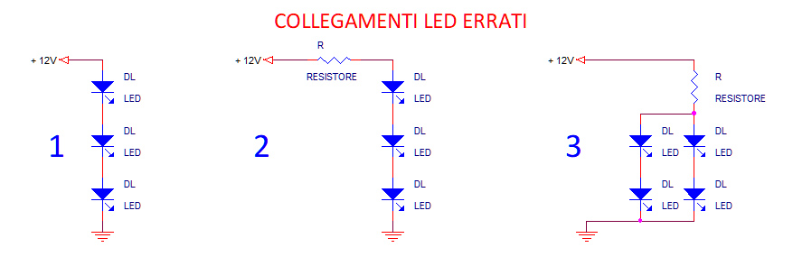
In the diagrams above we can find some connections that I have personally verified in some LED bulbs.
LED design error #1
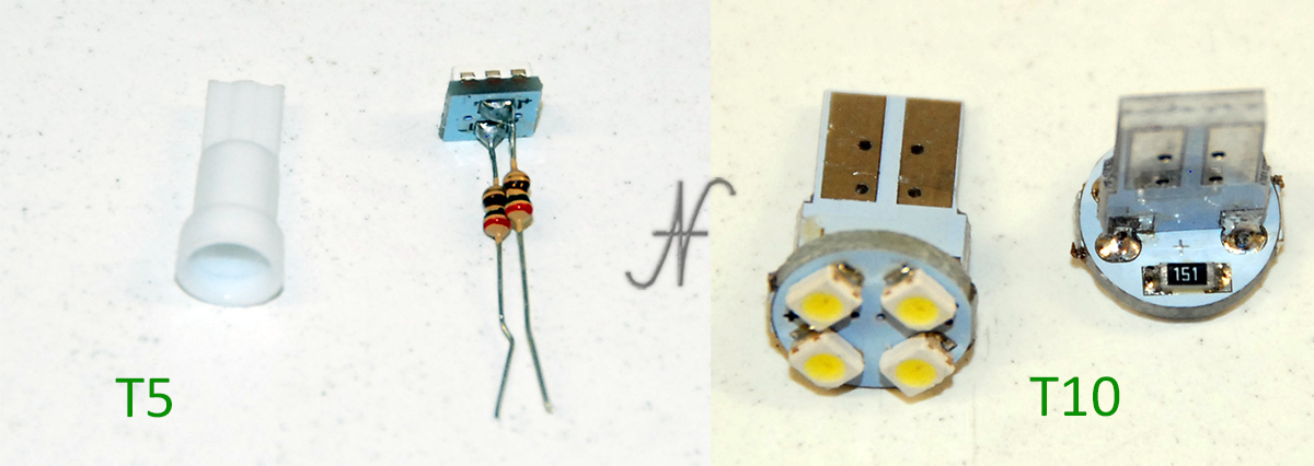
Nell'Example 1, who designed the LED lamp, believed that the LEDs were light bulbs and connected them in series without a current regulator (without resistor).
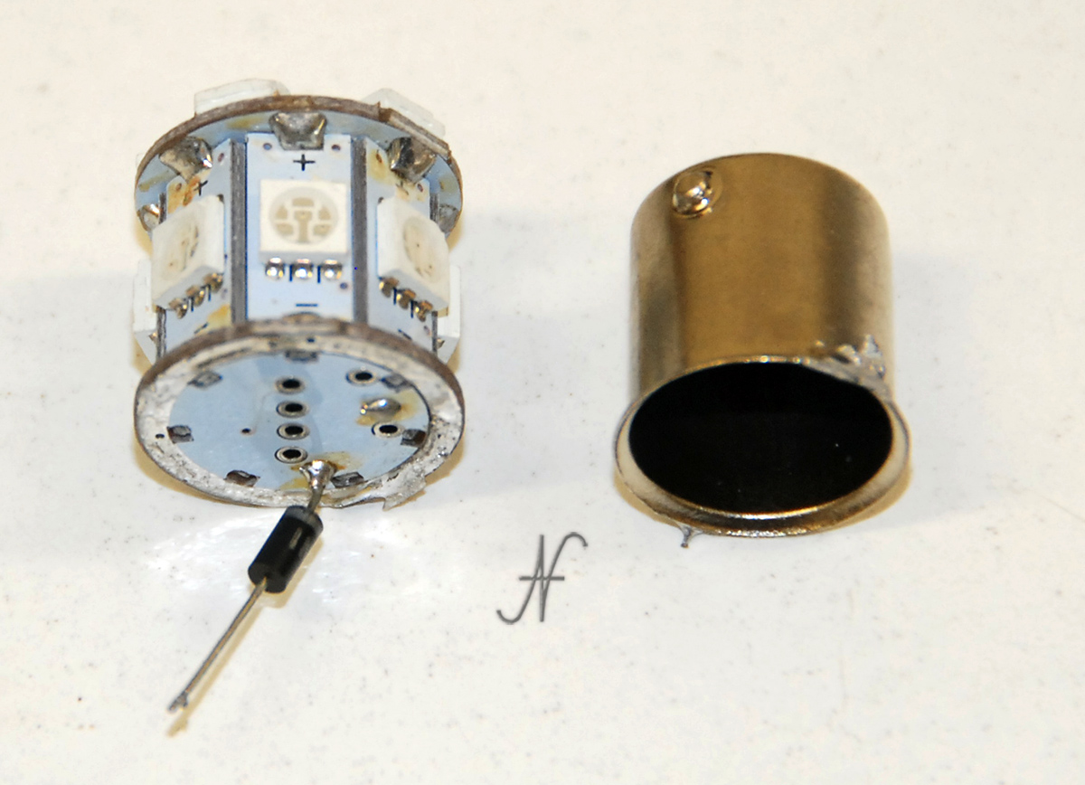
I personally found the bulb (photographed above) absolutely dim, with no resistors to regulate the LED current. The lamp was extremely hot and would not last more than an hour. Unfortunately, even by adding the appropriate resistors, the lamp was too dim to be mounted on my car. I may possibly use it in a nativity scene...
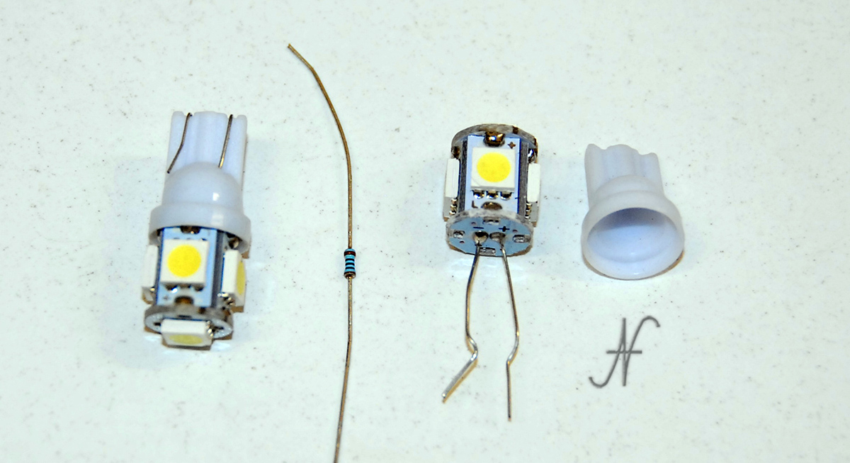
LED design error #2
Nell'Example 2, everything would seem correct: the LEDs are connected in series with a resistor that regulates their operating current (IF). It's a shame that such a configuration only works on paper and not in real life! I have personally purchased motorcycle grip light covers that lasted less than a season. They had the problem drawn in example #. 2. After experiencing this, I fixed it by rewiring the LEDs as I will indicate in the following paragraphs.
Let's see why the configuration of example n. 2 is incorrect. If we connect three LEDs in series, we have an estimated operating voltage of 3 times the single LED drop.
The voltage at the ends of the three LEDs is:
Vled = 3 * VF = 3 * 3.7 = 11.1V
Bene, se la tensione della batteria (Vbatt) è di 12V, il nostro "bravo" progettista di lampade a LED low cost calcolerà la resistenza (R) di regolazione della corrente operativa (IF) in questo modo, secondo la prima legge di Ohm:
R = (Vbatt - Vled) / IF = (12 - 11,1) / 0,02 = 45ohm
It will then find a resistor with a value similar to that of calculation, but that is actually existing on the market: 47ohm.
Too bad that, when the engine of our car or motorcycle is turned on, the voltage at the ends of the battery can exceed 14V! Making simple calculations, always using Ohm's first law:
IF = (Vbatt - Vled) / R = (14 - 11,1) / 47 = 0,062A
The IF current is now 62mA, capable of destroying the LED as it is too high, because it is higher than the maximum IF.
Even assuming we calculate the resistance value (R) for a voltage of 14V and not 12V (and therefore about 145ohm), we would have another problem: the brightness of the motor-off LED would be too low, as the IF current would be about 6mA, well below the 20mA we need.
The only solution is do not put three LEDs in series (if these have a high VF voltage like the one in our practical example), but put the LEDs in series two by two!
LED design error #3
Finally we have theexample number 3. This configuration is, unfortunately, very common among LED bulbs that can be purchased at a low price. We cannot exclude that the LEDs, although connected as in example no. 3, they work. However, there is a problem of balancing the IF operating currents.
We must therefore calculate the resistor (R) so that the generated current is double compared to the operating current of the single series of LEDs, as there are two series. Leaving aside the calculations (already seen in the previous example), we should use a 150ohm resistor (R), which ensures a total current of 40mA between the two series of two LEDs. Each series should draw 20mA. This is true enough, but not entirely. If we carefully analyze the datasheet of our example LED, we note that there is a relationship between VF (LED operating voltage) and IF (LED operating current). We find it in the graph of Fig. 4 on page 3. In short, we note that even a difference of 0.1V, of operating voltage tolerance (VF) between one LED and another, can cause different absorptions (IF) even of different mA.
This means that some LEDs may absorb a few mA more and others less. If the IF current of an LED exceeds the maximum allowed, or with that additional current it heats above the allowed junction temperature (Tj), the LED could be damaged. If the LED is designed well, with all the considerations listed above, an imbalance of currents would most likely not cause any damage. On the contrary, if the designer has calculated an IF current very close to (or even higher than) the maximum allowed, even a small imbalance could cause the LED to heat up disproportionately and damage it.
Correct design of LED bulbs
After seeing what not to do to design an LED lamp, let's now see some examples of a well-designed light bulb. Taking advantage of the techniques and schemes that I will provide, it will also be possible to correct poorly designed bulbs, or take advantage of the LEDs of non-working bulbs to make other, better lamps.
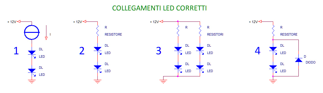
Remember that the LEDs must be driven in current (the IF current previously described) and not in voltage. The VF voltage will develop when the LED is crossed by the IF current. For low power lamps, the IF operating current, of a few tens of mA, can be conveniently generated by a resistor (indicated with R in theExample 2 of the correct schemes above).
Also from example no. 2, it is clear that the maximum number of LEDs that I recommend connecting in series under a single resistance is two. This applies to white LEDs with high brightness, not excluding that there are different LEDs, which have lower operating voltages (VF) and therefore allow them to be connected even in series of three or four (for 12V power supplies).
If you have the datasheets of the LEDs to use, I recommend retracing the calculations reported at the beginning of this article.
If the technical data of the LED is not available?
If, on the other hand, the technical data of the LED are not available, in a prudential way I would not travel more than 15-20mA on the series of the two LEDs (and in any case on the single LED, since the current that runs through the series of the two LEDs is equal to the current that runs through each LED of the series). I therefore recommend starting with a resistor (R) of 470ohm (1/4W of power) for the series of two LEDs. In the case of a single LED, I recommend starting with a 560ohm (1/4W) resistor. The values of the resistors are already calculated assuming a supply voltage of 14V and a voltage drop of about 3V LED.
When the first temporary assembly is carried out, it is possible to measure the actual current flowing through the LEDs using a tester. After the measurement, it will be possible to decide to increase the value of the resistors to reduce the absorption, or to reduce the value of the resistors to increase the absorption of the LEDs.
During the test, you need to be sure that the LEDs do not dissipate too much heat: paying attention not to get burned, it must be possible to hold a finger on the LEDs, feeling only a feeling of lukewarm. LEDs do not have to be absolutely hot.
To make lamps with more than two LEDs, it will be necessary to make several series of two LEDs, with their respective resistors (R) all the same, then connecting them in parallel as inExample 3.
Polarity of LED bulbs
Finally, for completeness of information, remember that LEDs work in one direction only, correctly connecting the + and - poles. In case of polarity reversal, the bulbs do not turn on.
Is it possible to damage LED bulbs by connecting them backwards?
If I said no, I would be lying. Carefully reading the datasheet of the LED taken as an example, we find another parameter that many overlook: the maximum reverse voltage, reverse voltage (VR). This is the maximum voltage that the LED can withstand when connected with the inverted poles. We can note that, in our example LED, the maximum reverse voltage VR = 5V. Therefore it is actually possible to burn an LED by reversing the polarity, because we could apply higher inverse voltages to it.
This parameter must be taken into consideration if we want to mount LED lamps in particular conditions, when it is possible that the polarity of the lamp may be reversed in the circuit (for example on the charging indicator light of the alternator of some vintage cars). In this case, you need to install a diode (D), type 1N4007, inside the LED lamp, after the resistor (R), as in example no. 4 of the previous image. The diode will protect the LED from reverse voltages: if connected with reversed polarity, the lamp will not light up, but will not be damaged.
To protect the LED against polarity reversal, solutions with a diode external to the LED are possible. What if we wanted to create a lamp that turns on even with reversed polarity? Or with alternating current? For the answers you will have to wait for the next articles!
In the next articles, I will also indicate solutions for avoid flickering of the LEDs in case of PWM power supplies (present in modern cars).
Per avoid the control unit error (which some call canbus error), which could indicate that the lamp is damaged, if it is replaced with an LED bulb, I wrote this article.