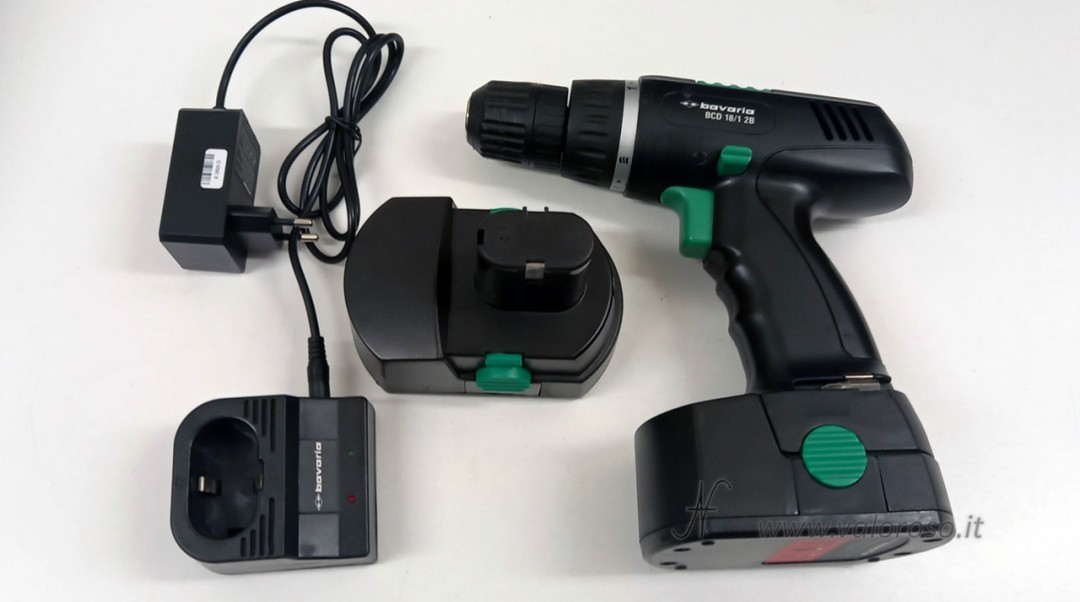
Here is the step-by-step procedure for replacing the battery pack of a drill driver, originally equipped with Ni-Cd cells, converting it to lithium ion (Li-Ion) batteries. I illustrate all the steps performed, the technical choices adopted and any ideas for future improvements.

The intervention was born from the need to recover an economical tool for which an efficient original battery pack was no longer available, avoiding the replacement of the entire drill.
Initial evaluation and choice of technology
The original battery pack was composed of 1.2 V Ni-Cd cells, for a real capacity of approximately 0.8 Ah, with obvious limitations in terms of autonomy and degradation over time. Among other things, the battery pack indicated a capacity of 1 Ah... evidently 0.2 Ah got lost along the way!
The same procedure for replacing drill driver batteries, described in this article, is also valid for Ni-MH packs, while in the case of existing Li-Ion packs it is often possible to keep the original charger, provided that compatibility is carefully checked. Instead, by changing battery technology, it is also necessary to replace the charger and modify the charging base.
The choice to switch to Li-Ion allows a net increase in capacity (approximately 3 Ah) at the same nominal voltage, improving autonomy, weight and availability of spare cells.

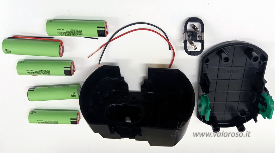
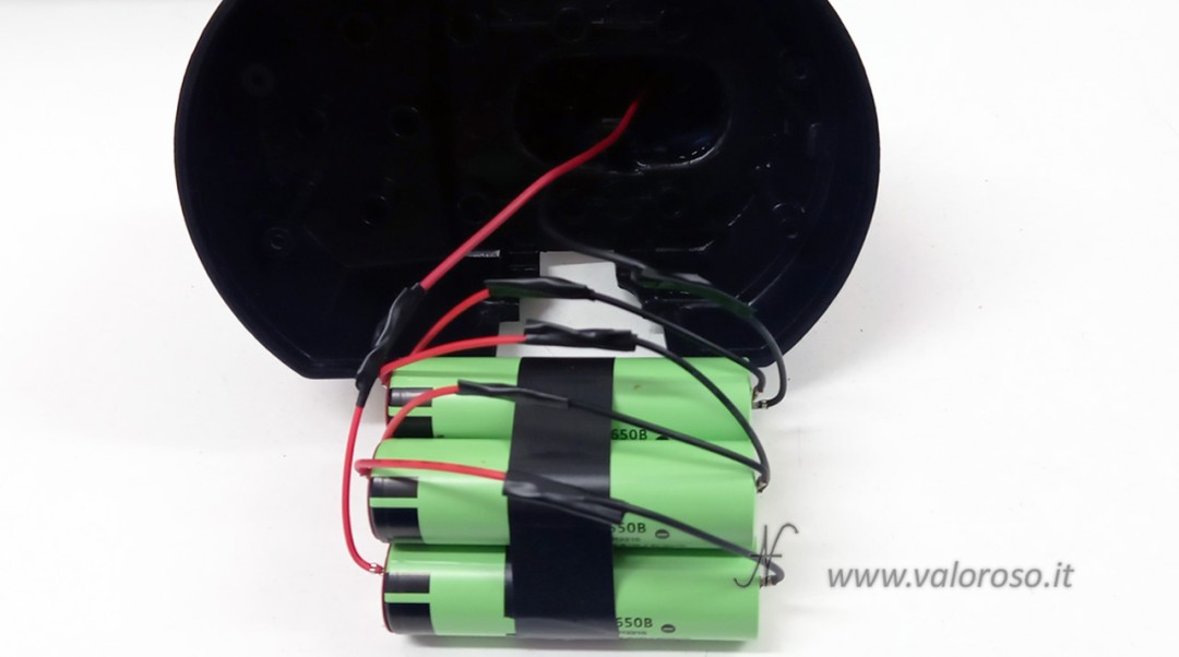
The first step consists in opening the battery pack container and completely removing the old Ni-Cd cells, taking care not to damage the original connector with the contact plates.
The new Li-Ion cells have a different voltage from the Ni-Cd ones, so the calculation of the number of cells needed must be carried out starting from the nominal voltage and not from the number of previous cells.
My battery pack being 18V, previously there were 15 Ni-Cd cells in series (1.2V x 15 cells). Now I have inserted 5 lithium ion cells of 3.7V each, of the 18650 type, in series. The batteries are already equipped with blades and electrical wires, so as to simplify the wiring operations as much as possible.
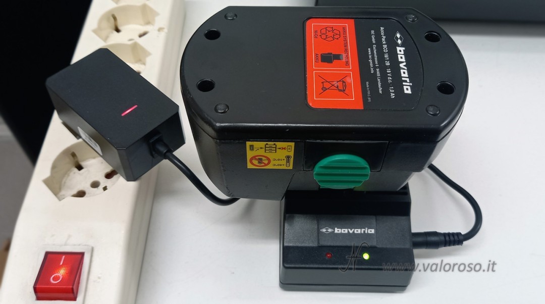
I had to purchase an appropriate charger, suitable for charging 5 Li-Ion cells in series (5S, 18.5 V, 21 V). The choice of charger was not random: I purchased a charger that was compatible with the number and type of new cells and that had a connector that fit into the charging base without too many problems.


Modification of the charging base for replacing the screwdriver batteries
The drill's original charging base was designed to work exclusively with the supplied Ni-Cd/Ni-MH charger and did not allow direct use of an external lithium-ion battery charger. For this reason a simple electrical modification must be carried out.
Inside the charging base, I proceeded to connect the input coming from the power connector directly in parallel to the output contacts towards the battery pack, respecting the polarity and bypassing the original electronics that are no longer necessary. In this way, the base becomes a mechanical support and contact adapter, allowing the external Li-Ion charger to properly power the battery pack.
Regarding the LEDs, I connected them for a function that is as particular as it is useless. When the battery (or charger) is connected with the correct polarity, the green LED lights up. If the battery (or battery charger) was connected with the polarity reversed (impossible however due to the mechanical keys), the red LED would light up.
Mechanical arrangement of cells and series connection
We initially proceed to mechanically couple the five 18650 cells (three lower and two upper), keeping all the positive poles on one side and all the negatives on the other. This arrangement facilitates both wiring and insertion into the container.
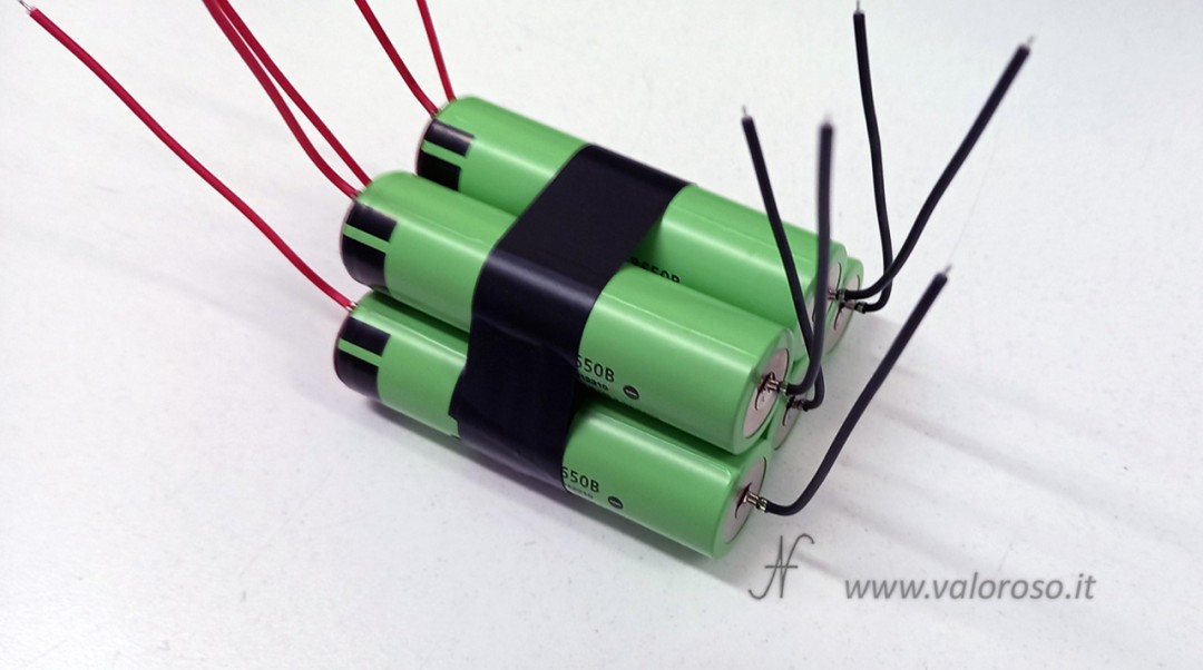
The electrical connection is made in series (5S): the negative of each cell (black wire) is connected to the positive of the next (red wire), the positive of the first cell (red) and the negative of the last (black) remain free and constitute the terminals of the pack.
To do the first tension tests, you can initially twist the wires. Then, you can proceed with tin soldering and careful insulation with insulating tape, which reduces the risk of accidental contact.

Adaptation and fixing of the original connector
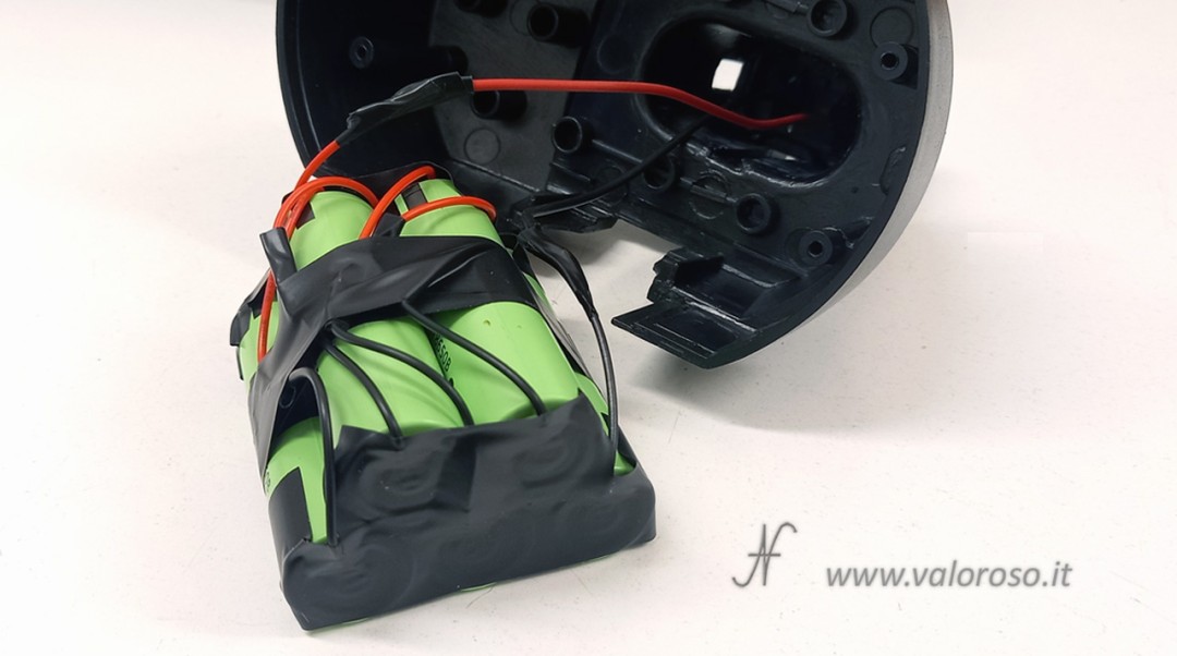
The red and black wires are first wrapped inside the slats, mechanically tightened by bending the slat with pliers and then tinned (the soldering mainly has a stabilization function).
This guarantees reliable electrical contact despite the fact that the strips are made of material that is not suitable for traditional welding.
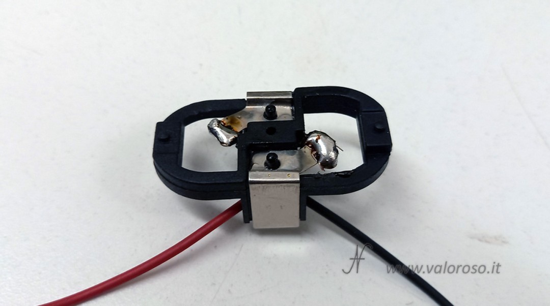
The blade connector, previously pushed into place by the Ni-Cd cells, is no longer mechanically supported. For this reason it must be glued to the base of the container with cyanoacrylate glue.
Obviously, the original polarity of the battery must be respected.

Once the connector has been connected to the battery pack (red with red, black with black), proceed with soldering and isolating the connections.
Particular attention is paid to the insulation of the positive and negative poles of the cells, to avoid any possibility of short circuit in the event of contact with metal parts inside the container (in my case they are only the clips of the battery locking clips in the screwdriver).
Internal fixing in the container
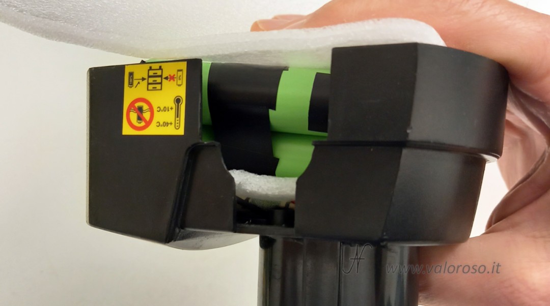
The Li-Ion cells are significantly more compact than the original Ni-Cd, leaving large empty spaces. To avoid internal movements, the battery pack must be blocked with filling material. I recommend using foam rubber, preferably self-extinguishing and insulating for electronic use.
The goal is to prevent internal vibrations and shocks when using the drill.
Closing the package and checking the charging
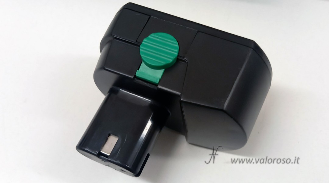
Once the fixing is complete, the container can be closed and screwed on. Finally we can try the new battery with the drill driver and the charging base.
The test on the charging base is successful. The green LED on the charging base indicates the correct polarity (and there was no doubt about this fact).
The battery charger LED indicates the charging status: red when charging, green when the battery pack is charged.
Security considerations and alternatives
The solution described is deliberately simple and does not involve the use of a BMS with thermal monitoring. In more advanced applications, or for work on behalf of third parties, it is possible to integrate a 5S BMS with voltage, balancing and temperature control, connecting each intermediate point of the cells.
The intervention carried out here demonstrates how, in many cases, it is more sensible to replace the battery pack rather than the entire drill, especially for economical models: a new low-end tool would in fact tend to present the same degradation problems in a short time. Repairing and reusing reduces waste, costs and environmental impact.