STROBE it's the project of a xenon strobe lamp, which I made when I was a boy. The lamp can flash autonomously, at a settable frequency, and moreover it can also be controlled from the PC, a microphone and other lights, through auxiliary modules.

Attention! All the stroboscope is connected directly to the 230 volt network, therefore it is very dangerous to touch each of its parts (also its feet 5 and 6). On the other hand, terminals 3 and 4 are electrically isolated. For safety, it is in fact advisable to interpose a 220 - 220 volt transformer between the network and the stroboscope.
In addition, the xenon strobe lamp is powered by a voltage of 600Vdc (between its A and K terminals) and the ignition voltage of the same lamp can reach even 4KV!
Xenon strobe lamp wiring diagram
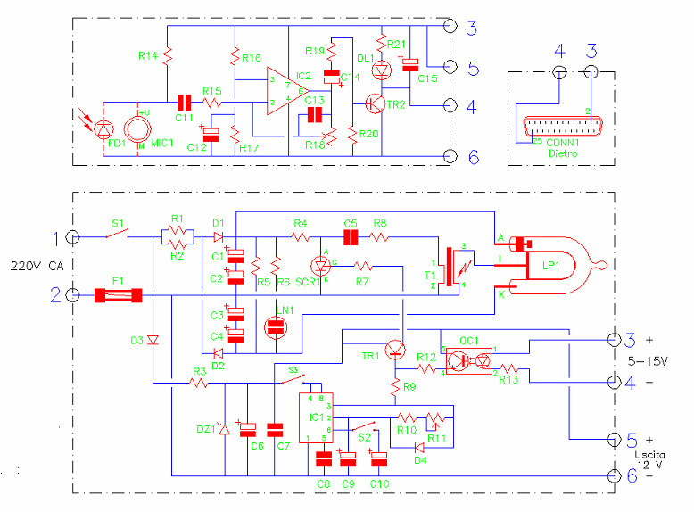
I / O:
- 1, 2 - Power voltage entrance (220-230vac), the components are not isolated, so do not touch them!
- 3,4 - Input to command the luminous impulse (isolated opto, 5-15vdc)
- 5, 6 - low voltage power output (12vdc, few but)
- S1 - General power switch
- S2 - internal oscillator scale (slow / fast flashes)
- S3 - switch to enable the oscillator (automatic flashing qualification)
- R11 - Lamp flashing frequency adjustment
Auxiliary module 1: triggers a flashing of the Xenon lamp when a flash of another lamp or a sound is detected.

Auxiliary Module 2: Connect the xenon strobe to the parallel port of the computer, to control flashes.
List of components, resistors:
- R1 - 1 Kohm 17 W (must dissipate heat)
- R2 - 1 Kohm 17 W (DEVE to dissipate the heat)
- R3 - 5600 OHM 5 W (DEVE to dissipate heat)
- R4 - 27 KOHM 1/2 W
- R5 - 1 MOHM 1/2 W
- R6 - 270 KOHM 1/2 W
- R7 - 330 OHM 1/4 W
- R8 - 100 OHM 1/2 W
- R9 - 1 KOHM 1/4 W
- R10 - 680 OHM 1/4 W
- R11 - 10 Kohm Logarithmic potentiometer
- R12 - 1 KOHM 1/4 W
- R13 - 470 OHM 1/4 W
List of components, capacitors:
- C1 - 22 UF 350 V or more, electrolytic
- C2 - 22 UF 350 V or more, electrolytic
- C3 - 22 UF 350 V or more, electrolytic
- C4 - 22 UF 350 V or more, electrolytic
- C1, C2, C3, C4, use capacitors with high discharge power
- C5 - 100 nf 630 in the doors
- C6 - 470 UF 25 V Electrolytic
- C7 - 100 NF Poliestere
- C8 - 10 NF polyester
- C9 - 47 UF 25 V Electrolytic
- C10 - 470 UF 25 V Electrolytic
Other electronic components:
- IC1 - NE.555
- TR1 - BC.237
- SCR1 - THIS.612
- OC1 - 4n.25
- D1 - 1N.4007
- D2 - 1N.4007
- D3 - 1N.4007
- D4 - Diodic at Germanio
- DZ1 - Diode Zener 12 V 1 W
- S1 - switch (power switch)
- S2 - switch
- S3 - switch
- T1 - Trust transformer for Xenon lamps
- F1 - Fusible 250 V 500 MA
- LN1 - Neon lamp without resistor
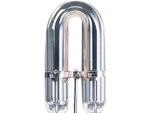
- LP1 - Xenon Stroboscopic lamp
Components of auxiliary modules, resistors:
- R14 - 4700 OHM 1/4 W
- R15 - 1 KOHM 1/4 W
- R16 - 10 KOHM 1/4 W
- R17 - 10 KOHM 1/4 W
- R18 - 470 KOHM trimmer
- R19 - 470 OHM 1/4 W
- R20 - 100 KOHM 1/4 W
- R21 - 820 OHM 1/4 W
Components of auxiliary modules, capacitors:
- C11 - 100 NF Polyester
- C12 - 10 UF 25 V Electrolytic
- C13 - 220 PF ceramic
- C14 - 2,2 UF 25 V Electrolytic
- C15 - 100 UF 25 V Electrolytic
Other components of the auxiliary modules:
- IC2 - do.741
- Mic1 - Electret pre -amplified microphone capsule
- FD1 - fotodiodo BPW.34
- DL1 - diodo led
- TR2 - BC.237
- CONN1 - Battery connector, 25 male poles (for the PC LPT door)
Analysis of the wiring diagram of the xenon strobe
The voltage taken from the 230 Vac network, via R1 and R2, is straightened and duplicated from D1 and D2 and charges the capacitors C1 C2 C3 C4 with a total potential of about 600 V. This direct voltage is used to power the XENON lamp, which will emit a flash only if there is a very high voltage peak on its central terminal. This peak is provided by T1 when a small pulse on the GATE of SCR1 will immediately discharge C5 into T1.
The two resistors R1 and R2 must withstand a high current, due to the flashes (short circuits) of LP1. For the same reason, the 350 V 22 uF capacitors were placed in a two-to-two series instead of just one 10 uF capacitors. By not adopting these precautions, both the C1 C2 C3 C4 capacitors and the R1 and R2 resistors will soon be destroyed.
T1 must be a four-terminal XENO lamp ignition transformer. For some transformers, R8 must be eliminated.

Operation of the xenon strobe lamp
The real novelty of this stroboscope is however in the IC1 oscillator, which allows to obtain a wide range of frequencies (flashes of light). With S2 closed the lamp will flash slowly (up to an impulse every three seconds), with S2 open this will flash faster (up to 10 and more impulses to the second).
Another novelty of this circuit is to be able to connect it to any electronic device via OC1 (to deactivate the stroboscope oscillator, open the S3 switch). In order for a flash to obtain, it will be necessary to give tension (5-15 V) to terminals 3 and 4 of the stroboscope.
You can, for example, connect it to the auxiliary circuit that allows you to flash LP1 to the rhythm of music (with MIC1) or when FD1 is hit by a beam of light. The R18 trimmer of this interface serves to adjust the sensitivity.
It is also possible to connect this stroboscope also to a compatible IBM computer, via the LPT1 (printer) and the Conn1 connector. Terminals 3 and 4 of the stroboscope will be connected respectively to feet 2 and 25 of the computer LPT1 socket.
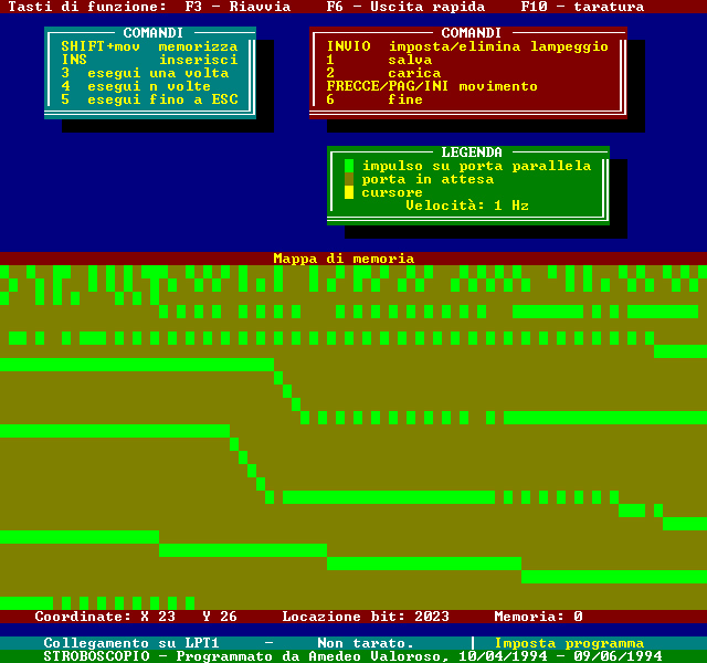
PC connection of the xenon strobe
I programmed the xenon strobe lamp software in QuickBasic for DOS. The software allows you to set the flashes of the lamp according to the time, as well as to save and load all the flashing sequences.
Other programming examples
The following programs are in basic language of the time (Gwbasic, Qbasic, Tbasic, etc ...):
   10 DEF SEG=0: PN=PEEK(1032)+256*PEEK(1033): DEF SEG
   ' Indirizzo della porta LPT1 su variabile PN
   ...
   ...
   100 OUT PN,255: OUT PN,0  ' Lampo dello stroboscopio
Line 10 prompts the computer to place LPT1 port memory. When a certain condition occurs in the program, the check will be sent to line 100, to get a flash. If the computer is too fast (it does not happen even with the 486), the line 100 will be replaced with the following:
100 OUT PN,255: FOR T=1 TO n: NEXT T: OUT PN,0
n is a number directly proportional to the speed of the computer.
This program flashes every S seconds (finally, press a key to exit):
   10 S=1  ' Tempo che trascorre tra due lampi (secondi)
   20 DEF SEG=0: PN=PEEK(1032)+256*PEEK(1033): DEF SEG
   30 WHILE INKEY$=""
   40 IF TIMER>=T+S THEN T=TIMER: OUT PN,255: OUT PN,0
   50 WEND
This program flashes every time you press ENTER (press ESC to exit):
   10 DEF SEG=0: PN=PEEK(1032)+256*PEEK(1033): DEF SEG
   20 I$="": WHILE I$="": I$=INKEY$: WEND
   30 IF I$=CHR$(13) THEN OUT PN,255: OUT PN,0
   40 IF I$=CHR$(27) THEN END
   50 GOTO 20
The following program emits programmable flashes, changing the bytes (0 - not flash; 1 - flash; 2 - fine; 3 - repeat from the beginning) separated by a comma of the instructions given. The weather is given by S (press a key to exit):
   10 S=0.4 ' Tempo di lettura dati (secondi)
   20 DEF SEG=0: PN=PEEK(1032)+256*PEEK(1033): DEF SEG
   30 RESTORE: WHILE INKEY$=""
   40 IF TIMER>=T+S THEN T=TIMER: READ X: ON X GOTO 70,60,30
   50 WEND
   60 END
   70 OUT PN,255: OUT PN,0: GOTO 50
   80 ' Dati (si possono inserire anche altre linee DATA)
   90 DATA 1,0,1,1,1,0,1,0,1,1,1,1
   100 DATA 1,0,1,2
Add, 2 o, 3 to the end of the last date depending on that the program should come out or resume the cycle from chief.
Project start: January 1994. State: for technical publication.