SPTEL è un rilevatore di linea telefonica impegnata, che ho progettato quando avevo poco più di 15 anni: si tratta di un LED che si accende quando la linea telefonica è impegnata da un apparecchio telefonico in conversazione. Questo mio progetto è stato pubblicato sulla rivista "Elettronica Pratica, Dicembre 1993".

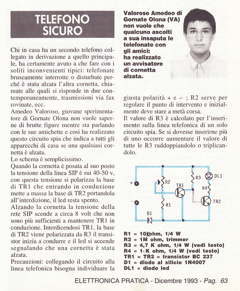
SPTEL components
Resistors:
R1 - 10 K ohm, 1/4 W
R2 - 1 M ohm, trimmer
R3 - 4.7K ohm, 1/4W (see text)
R4 - 1K ohm, 1/4W (see text)
Other:
TR1, TR2 - transistor BC 237
D1 - silicon diode 1N4007
DL1 - diodo LED
SPTEL, busy telephone line indicator, description
For those who, like me, have more than one telephone at home, it is often a problem to be able to make a call without someone picking up the phone and starting to dial numbers and talk, perhaps excluding the person who was speaking before, thus ruining an important phone call. But this is not the only drawback of having more than one device on the SIP line. When it rings, it can happen that two people answer at the same time. But there's more: how should I notify someone that I'm calling, so as not to be disturbed? Sure, you can shout it, but it's not the ideal solution for those who have a large house and neighbors with open ears...
Well, by building this microscopic circuit, a busy phone line detector, you will have a constant alert of the status of the phone line. More precisely: when someone picks up the handset, the indicator lights located in the desired places will light up, alerting you that the phone is already busy. When the phone is free (handset down), the LEDs will turn off.
Knowing that someone is already on the phone, no one will dream of picking up their receiver, unless they want to spy... But at this point the brightness of the LED will decrease, thus warning that they are being listened to.
Owning a FAX, the circuit is useful to know if it is still in operation, thus avoiding interfering by raising a handset.

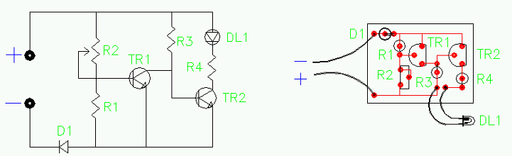
Circuit operation
The principle of operation of this circuit is very simple, and is based on the conduction and interdiction of transistors.
When the telephone handset is hung up, i.e. the SIP line is free, the voltage present on the line will be around 40-50 Volts. This voltage will be lowered by the resistive divider R2 - R1, while remaining at a level sufficient to bring TR1 into conduction. TR1 will then prevent R3 from exciting TR2 (by connecting its base to negative), so the LED will be off.
By lifting the telephone handset (or with answering machine, FAX, etc... in operation) the voltage present on the telephone line will be around 8 Volts, the resistive divider will reduce the voltage which however will be insufficient to bring TR1 into conduction. With TR1 blocked, the resistor R3 will be able to carry a weak positive current to TR2, which will manage to conduct voltage and turn on DL1.
When the phone rings, DL1 flashes fast and brighter.
D1 is necessary to avoid burning TR1 or TR2 when the telephone rings, and to save the circuit if the polarity of the power supply were to be reversed (to establish the + or - of the SIP line it is sufficient to use a tester).
Telephone line busy detector calibration
The calibration of the circuit is simple, as only the R2 trimmer has to be retouched.
Before giving current to the circuit, it is necessary to rotate the slider of R2 halfway through, in order to prevent it from bringing too much current to TR1.
By connecting the circuit to the SIP line, the LED should be turned off (if this does not happen, gradually rotate the slider of R2 towards the positive, until the LED turns off). Raising the phone's handset, the LED will light up and lowering it will turn off (rotate the R2 slider appropriately, if necessary).
If the LED flashes when speaking to the handset, turn the R2 trimmer away from the positive.
Then check if the circuit works correctly with all telephone devices.
Useful tips
Applying a single circuit on the SIP line, R3 can also be 4.7 K ohms, but if you were to install more circuits, it is better to raise its value to 8.2 K ohms or even 10 K ohms, since too much absorption on the line would make the SIP believe that a handset is raised, preventing you from receiving phone calls.
If the brightness of the LED is too low, the value of R4 can be increased from the current 1000 ohms to 820 or 470 ohms (also considering the number of circuits installed, to avoid lowering the volume of the telephone handset too much).
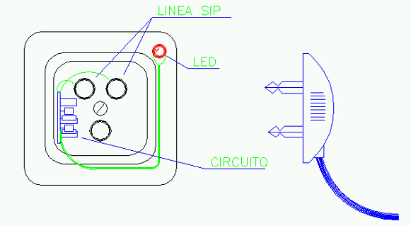
Given the small size of the millefori base, I installed the circuit of the telephone line detector engaged in the phone socket, protruding the LED from a small hole made in its corner.

Project start: May 1993. State: for technical publication.