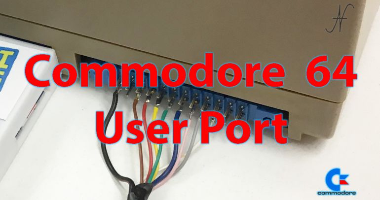
I have always found it interesting to consider the computer not only as an independent entity, but able to control other equipment. It is possible to check the user port of the Commodore 64 for this purpose: that is, integrate the computer with the surrounding environment.

I had already done some experiments to connect the Commodore 64 to the home automation system of the house: In that experiment, User Port was in fact used to communicate with a WiFi modem.
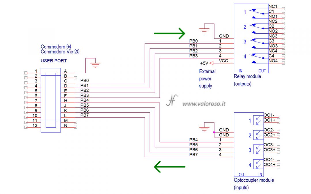
In the experiment of this article, however, the PB0-PB7 Pin of the User Port of the Commodore 64 are used directly to command two interface cards.
Commodore 64 User Port interface cards
There are different types of interfaces to connect to the Commodore 64 User Port. In this article I therefore describe:
- an output card with 4 relays, optically isolated;
- an entrance interface, with 4 ops -melatori.
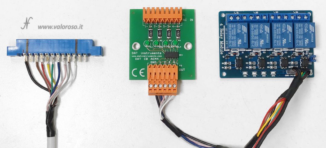
The interfaces are used to command loads and to acquire states. The card with 4 relays can be used to control high and low voltage loads. On the contrary, the opto-isolated input card can only be used to measure the presence of mains voltage. Of course, there are also low voltage versions.

User Port Inputs and Outputs
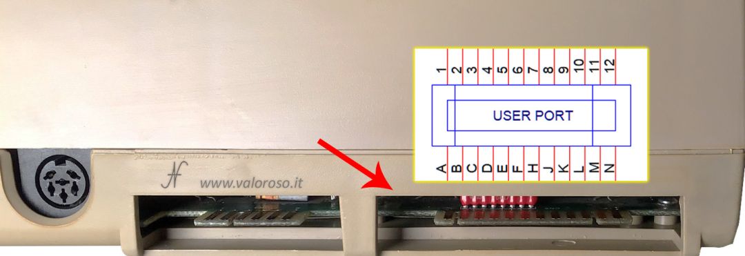
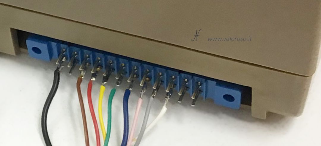
For the theory enthusiasts, here are some schemes! Of the User Port of the Commodore 64, we will use only the 8 PINs of the B hold B: I PIN PB0, PB1, PB2, PB3, PB4, PB4, PB5, PB6 and PB7. For this they abbreviate themselves with PB0-PB7. The PB port is connected to the feet C, D, E, F, H, J, K and L Della User Port. There is attention to the fact that on the blue connectors that are purchased to interface with the User Port (3.96mm edge type with 24 poles), the letters are not the same as those of the User Port. Therefore the pins must be identified manually.
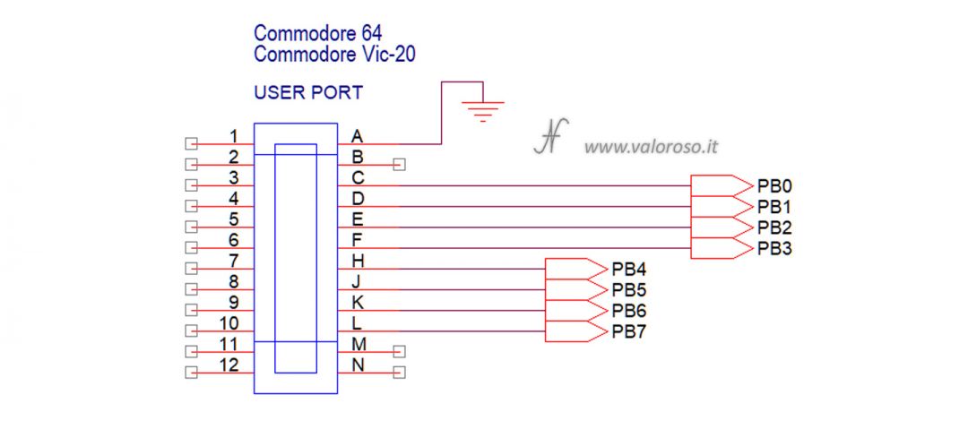
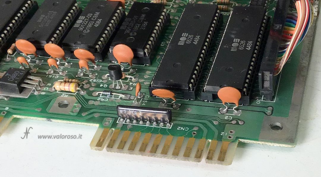
The PB0-PB7 pins of the User Port, as can be seen from the diagram obtained from the Commodore 64 Service Manual, are directly connected to the CIA U2 chip of the Commodore 64: the MOS 6526, whose datasheet is attached at the end of this article.
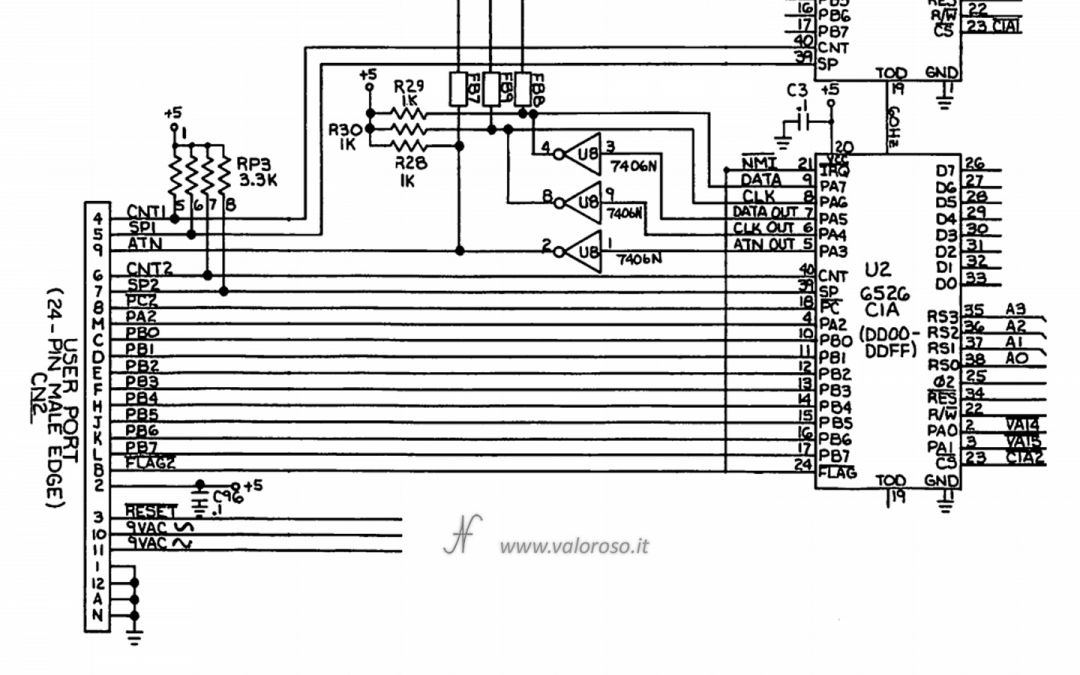
The MOS 6526 is a chip in NMOS technology, so it is able to deliver a satisfactory current only on logic level 0. In other words, it is as if it behaves like a small switch to ground. On logic level 1 it is not possible to draw a satisfactory current, but it should be considerably amplified.
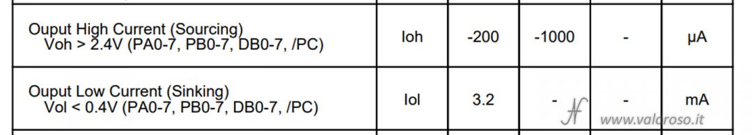
For this reason, the card with 4 relays (optically isolated) activates the outputs when the corresponding input is brought to ground, with a current of at least 2 mA. The Commodore can deliver 3 mA, so the current is sufficient.

Just to make sure, the relays are powered by an external 5V power source, not loading and thus dirtying the feeding of the Commodore 64. From the user port, therefore, we only take the signals and not the power supply.
As for the opposite direction, i.e. allowing the Commodore to read states or the presence of a voltage, here too it is advantageous to use schede optoisolate open collector. If there is a voltage at the entrance of the photo, the exit of the card (and therefore the entrance pin of the User Port of the Commodore 64), goes to Massa. If there is no tension at the entrance of the photo, the exit of the card remains free and therefore the User Port input Pin is free to go on a logical level 1, by means of the pull-up resistor (and also other circuits) already present inside the computer chip (Mos 6526) of the computer.
Pins PB0-PB7 can be individually configured as inputs or as outputs. For convenience, I used PB0-PB3 pins as outputs and PB4-PB7 as inputs.
Basic commands for Commodore 64 User Port outputs
To control the inputs and outputs of the User Port from the Commodore, you can use simple instructions in Basic.
Relative to uscite a relay, it is possible to activate a relay using the command:
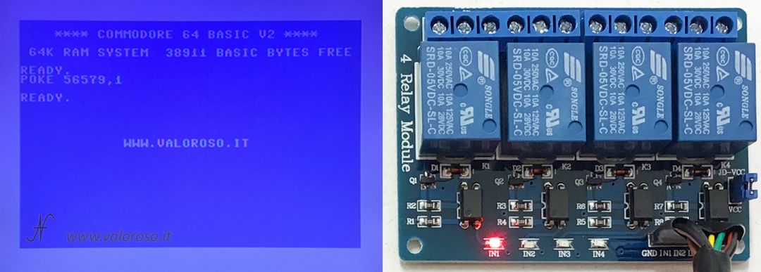
POKE 56579, numero
The value number In essence, it represents the PIN (or PIN) of exit to be activated, to be calculated with the powers of 2: 2 ^ (number_relay - 1).
To activate relay 1, pin PB0, number = 2 ^ (1 - 1) = 2 ^ 0 = 1:
POKE 56579, 1
Activate relay 2, pin PB1, number = 2 ^ (2 - 1) = 2 ^ 1 = 2:
POKE 56579, 2
To activate relay 3, pin PB2, number = 2 ^ (3 - 1) = 2 ^ 2 = 4:
POKE 56579, 4
Finally, to activate relay 4, pin PB3, number = 2 ^ (4 - 1) = 2 ^ 3 = 8:
POKE 56579, 8
If several relays are to be activated at the same time, the previously calculated values must be added together. For example, to activate relay 2 and relay 4, the command is:
POKE 56579, 10
The deactivation of the relay is obtained simply by subtracting the corresponding number. At the limit, to turn off all the relays, you can type:
POKE 56579, 0
Warning! Actually the command POKE 56579, number is used to set the pin of the PB port as the output! As soon as it is set as an output, the corresponding pin immediately goes to logic level 0 (to ground), therefore activates the relay.
In addition, all 7 pins of the PB port can be used as outputs. For convenience, I have only used the PB0-PB3 pins as outputs.
Basic commands for User Port inputs
With regard to the entered optoisolati, to read the value corresponding to the status of the inputs, use the following command:
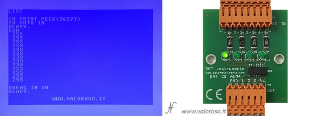
PRINT PEEK(56577)
The returned value ranges from 0 to 255. Each input, when there is voltage, it leads to mass, therefore the corresponding bit goes to 0. To check, therefore, if the photo accommodation entrance is present, you can proceed in this way:
IF ( PEEK(56577) AND 2 ^ (numero_fotoaccoppiatore + 4 - 1) ) = 0 THEN ...
The sum number_photocoupler + 4 è perché, in questo esperimento, i fotoaccoppiatori 1, 2, 3 e 4 sono collegati su PB4, PB5, PB6 e PB7. Ricordo, anche, che i piedini della porta PB si portano a 1 logico in caso di assenza di tensione. Per verificare, quindi, l'assenza della tensione, è sufficiente togliere "= 0" dal comando.
Check the presence of voltage in the optocoupler 1 input, pin PB4:
IF ( PEEK(56577) AND 2 ^ 16 ) = 0 THEN …
No voltage:
IF ( PEEK(56577) AND 2 ^ 16 ) THEN …
To check the presence of photocoupler 2 input voltage, pin PB5:
IF ( PEEK(56577) AND 2 ^ 32 ) = 0 THEN …
No voltage:
IF ( PEEK(56577) AND 2 ^ 32 ) THEN …
Check the presence of voltage in the photocoupler 3 input, pin PB6:
IF ( PEEK(56577) AND 2 ^ 64 ) = 0 THEN …
No voltage:
IF ( PEEK(56577) AND 2 ^ 64 ) THEN …
Finally, to check the presence of photocoupler 4 input voltage, pin PB7:
IF ( PEEK(56577) AND 2 ^ 128 ) = 0 THEN …
No voltage:
IF ( PEEK(56577) AND 2 ^ 128 ) THEN …
Using the inputs of the photo accommodation tab with alternating tensions, the situation is slightly complicated, as the corresponding PB pin oscillates between 1 and 0 with a certain frequency (for example 50Hz if you connect the entry to the voltage of the electrical network).
In this case, it is necessary to carry out several readings, before discriminating the value of presence or absence of voltage.
As already mentioned, it is possible to use the entire PB port as an input, but, for convenience, I used only the PB4-PB7 pins as inputs.
Documentation
To conclude, I attach:
- il Commodore 64 Service Manual, where the User Port scheme is present
- il CIA chip datasheet: the MOS 6526 (by Markku Alén)
Finally someone who takes care of the User Port of the C 64
What can we still control through the user port of the C64, in addition to your projects so far?
Well, I would say that the scope is limited only by the imagination! I connected the Fiat X1/9, the Christmas tree, the electric stove, the coffee machine ... you can do everything!
Very interesting!
Can I know the specifications of the two cards (relays and photocouplers)?
If I wanted to make a bidirectional parallel communication optoisolated with another device, should I limit myself to 4 input opto and 4 outgoing or is there a way to take advantage of all 8 bits in I/O guaranteeing isolation anyway?
Thank you (I'm a newbie)
Grazie! La schedina con i relay si trova su Amazon tranquillamente, cercando "relay fotoaccoppiatore per Arduino". Relativamente alla scheda ingressi, quella la produciamo in ditta, ma non è per uso hobbistico. Non so se ne esistano di già pronte. Al limite, potresti utilizzare una scheda relay collegata "al contrario": le uscite del relay comandano gli ingressi del Commodore. Costruire una scheda 8 IN e 8 OUT (ma anche di più) è possibile, ma non è immediato come sfruttare direttamente i pin della User Port.