In this video, we see how to improve the picture quality of the Commodore 64, 128 and Commodore 16, using an S-Video cable instead of the Composite Video (CVBS) cable.

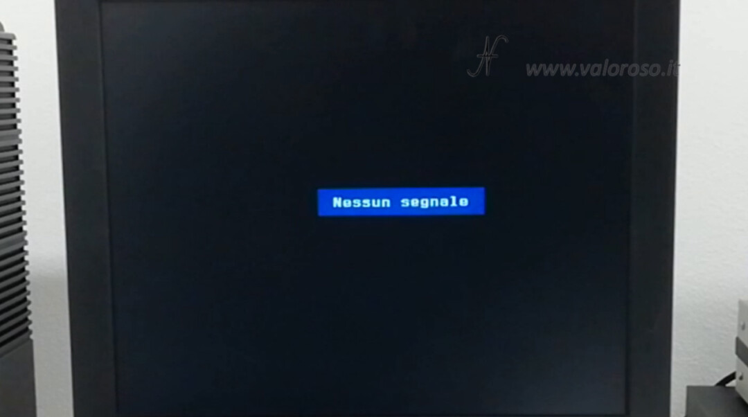
If you connect your Commodore to a modern LCD, plasma or LED television via a composite video cable, the image quality may be very bad.
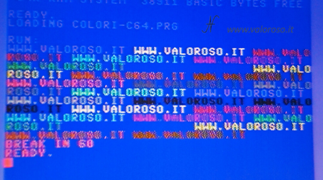
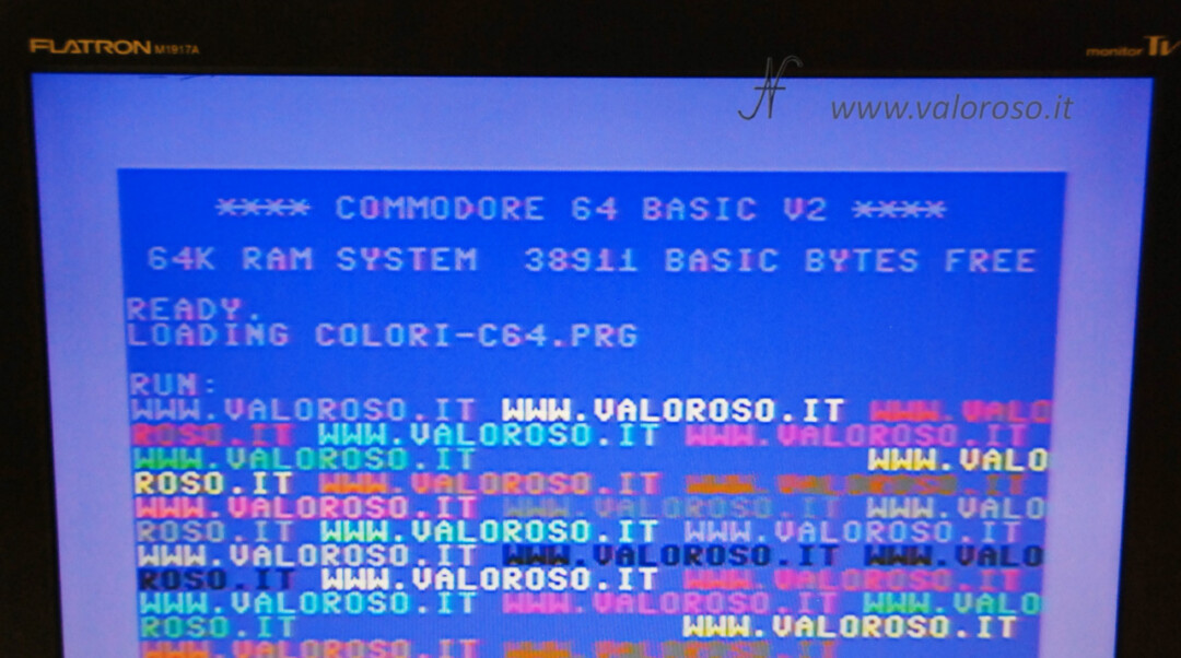
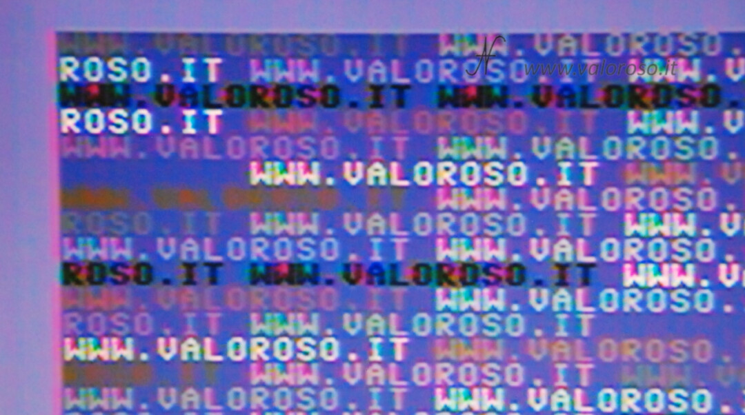
Using the CVBS composite video cable (the one with the three yellow, white and red plugs, so to speak) you can see several defects on the colored texts on the monitor.
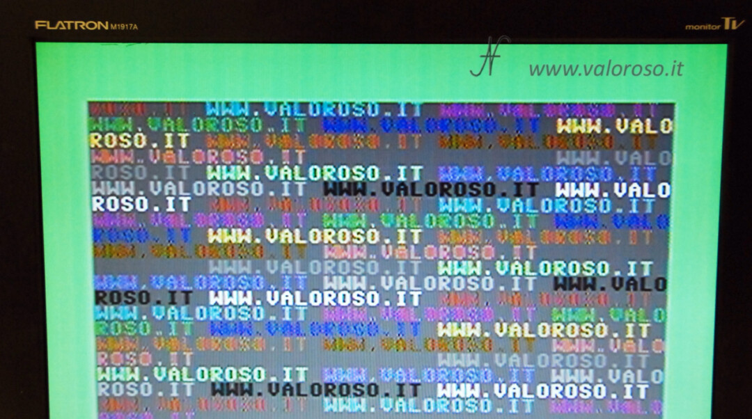
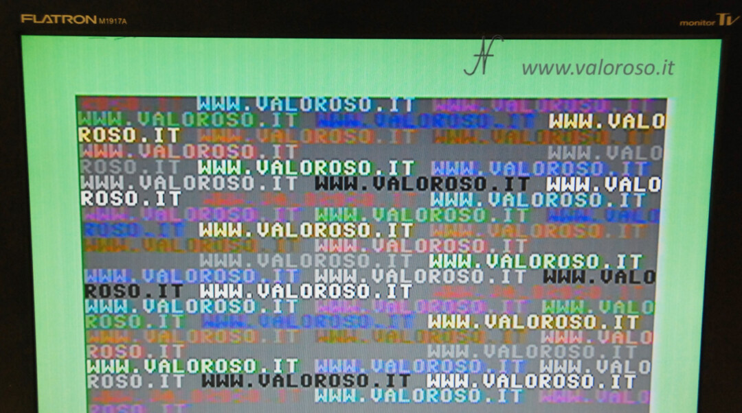
By using an S-Video cable, the image quality improves dramatically.
Obviously, it is not possible to pretend that the image is comparable to that of a modern computer!

If you follow this article to the end, you will discover how to build an S-Video cable, why a resistor is needed on the chroma signal and why it is good to use the S-Video connector, the 4-pin miniDIN connector, instead. the SCART socket.
Obviously you can find these cables already built and tested for a few euros, but I still suggest you read the article, or watch the video, to understand which is better to choose.
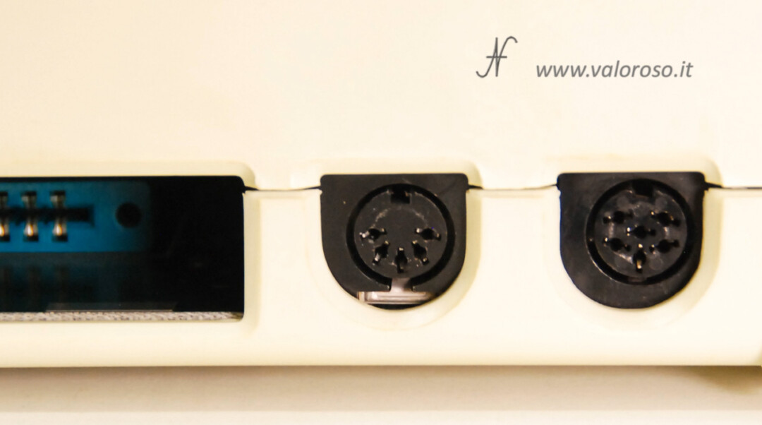
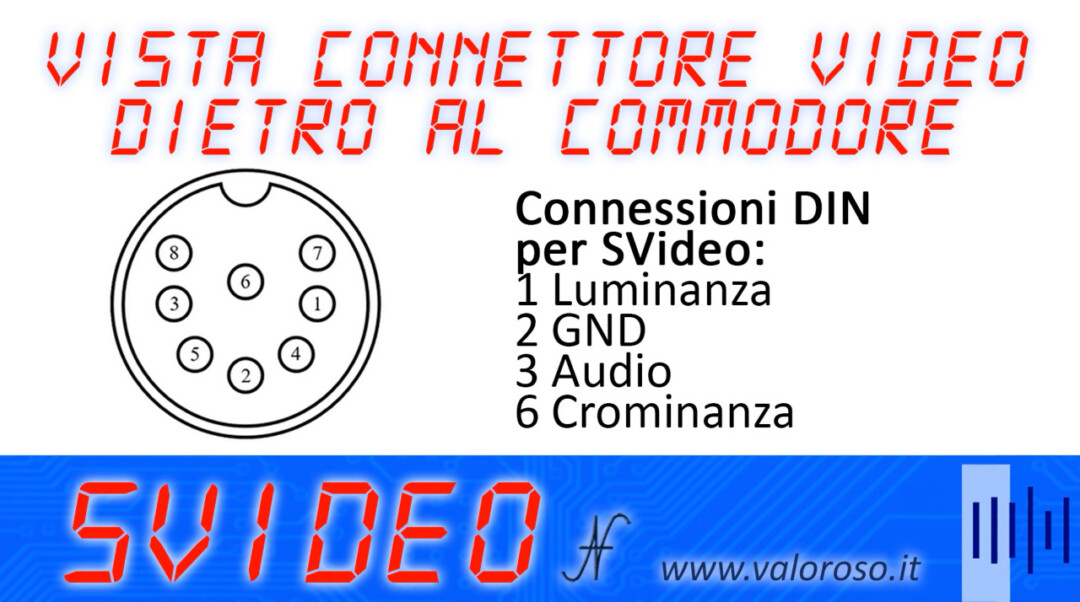
DIN 8 video connector to improve Commodore picture quality
Before buying or building the S-Video cable, check that your Commodore has an 8-pole DIN video output and not a 5-pole one.
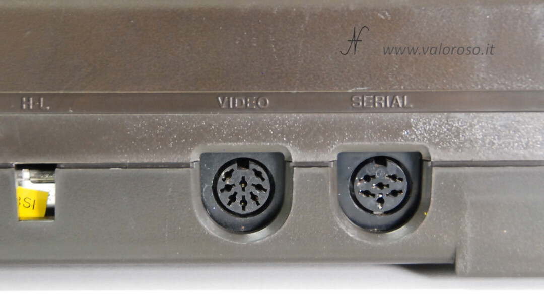
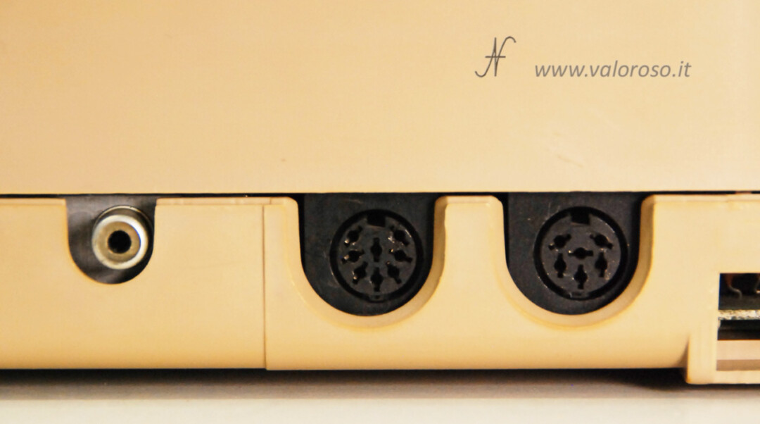
If the video connector on your computer has only 5 pins, such as in my Commodore Vic20, you will not be able to use an SVideo cable. In this case, you will have to settle for the quality of the CVBS composite video cable.

Components to build an S-Video cable for the Commodore
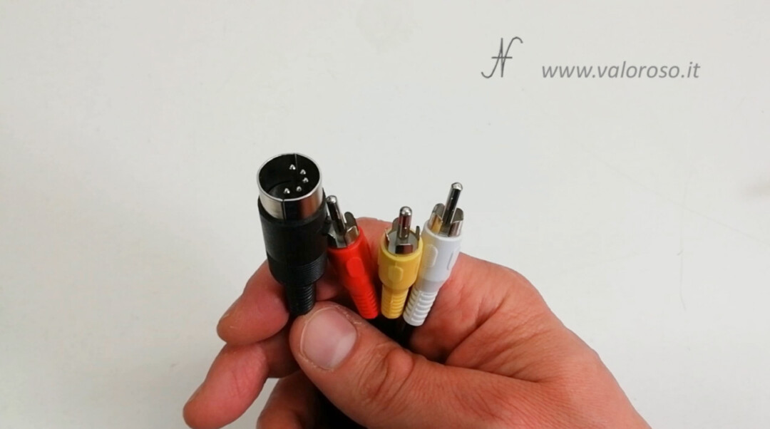
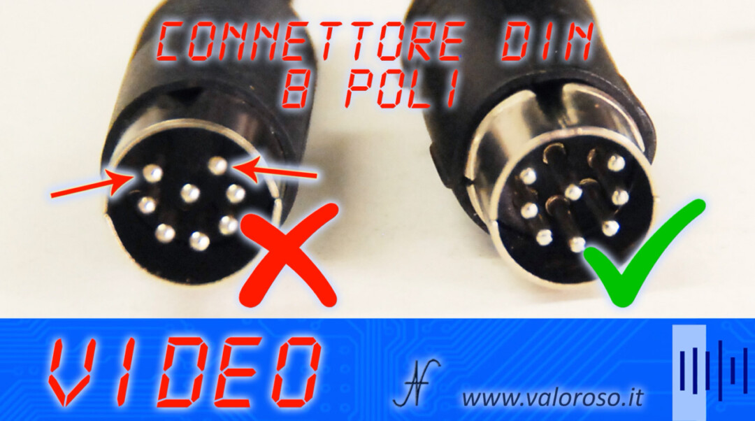
To build an SVideo cable to improve the image quality of the Commodore 64, 128 and 16, first you need to get the 8-pin DIN connector. Not all 8-pole DIN connectors are suitable: the video one is 262 °, male.
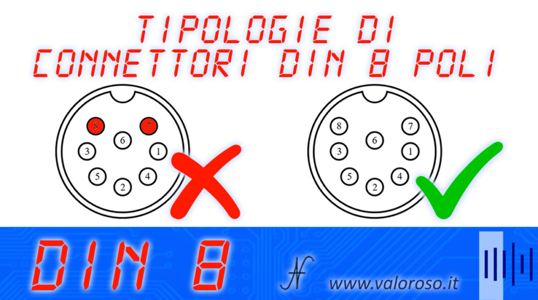
The difference is in the two pins 7 and 8, which must not be in a circle, but almost on a line with respect to the other side pins.
If you do not find a suitable connector, you can still buy an 8-pin DIN connector with 360 degree pins, but you will have to remove pins 7 and 8 by pulling them out with pliers.
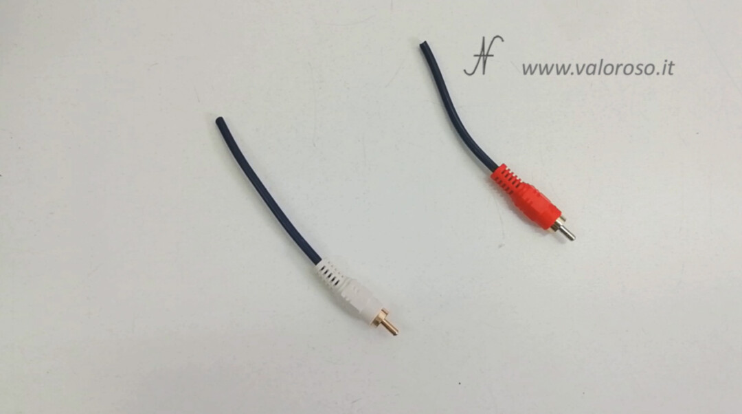
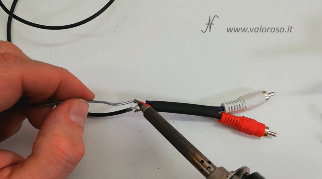
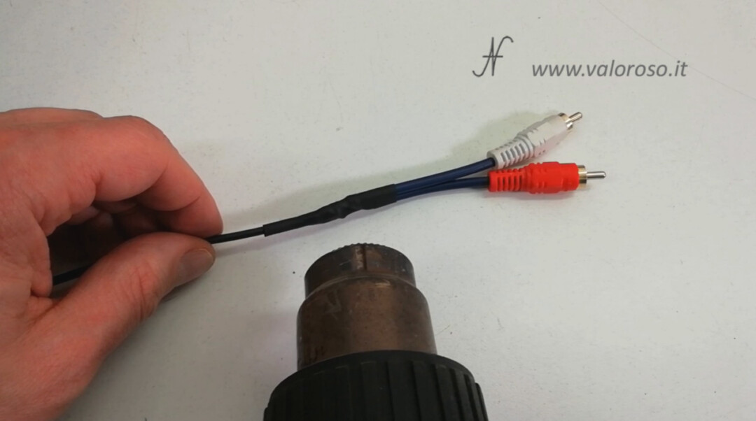
You also need the two RCA audio connectors, which you can recover from a cable you don't use, or you can buy them with the rear pins to be soldered. You also need the audio cable, mono, shielded.
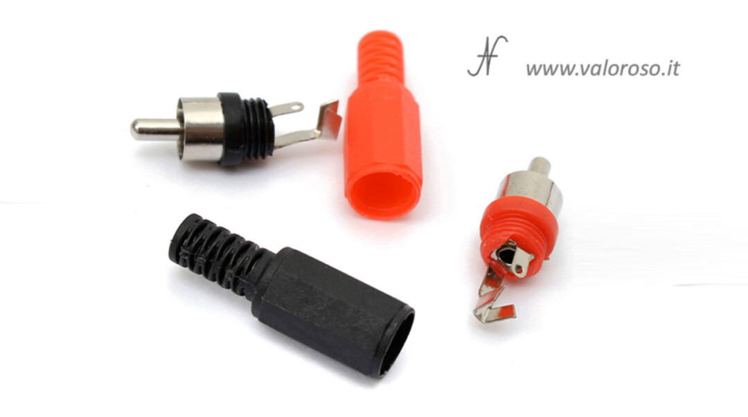
Of course, you need an S-Video connector, 4-pin male miniDIN. You can get it from an aldready built S-Video cable, as I did, or you will have to get the miniDIN solder connector and an SVideo cable, which contains 2 shielded cables: one for luminance (luma) and one for chrominance (chroma).
I preferred to use a SVideo cable with pre-cabled connectors, of suitable length. This way, from a cable with two SVideo connectors, I can build two cables for the Commodore.
Pay attention to the outer diameter of the cables: Both the audio cable and the S-Video cable must fit into the 8-pin DIN connector shell!
Finally, a resistor is needed for the chroma signal. If you keep following the video, you will see what happens if you don't mount the resistance!
I used a 75 ohm resistor, with which I got the best results with my monitors, but on some blogs they suggest using a 300 ohm resistor.
How to Build an S-Video Cable to Improve Commodore Picture Quality
You will need a soldering iron, solder, a pair of electrician's scissors, some electrical tape and a support to hold the cables and connectors when you solder them. Optionally, you may need heat shrink tubing with a lighter or a specific hot air blower.
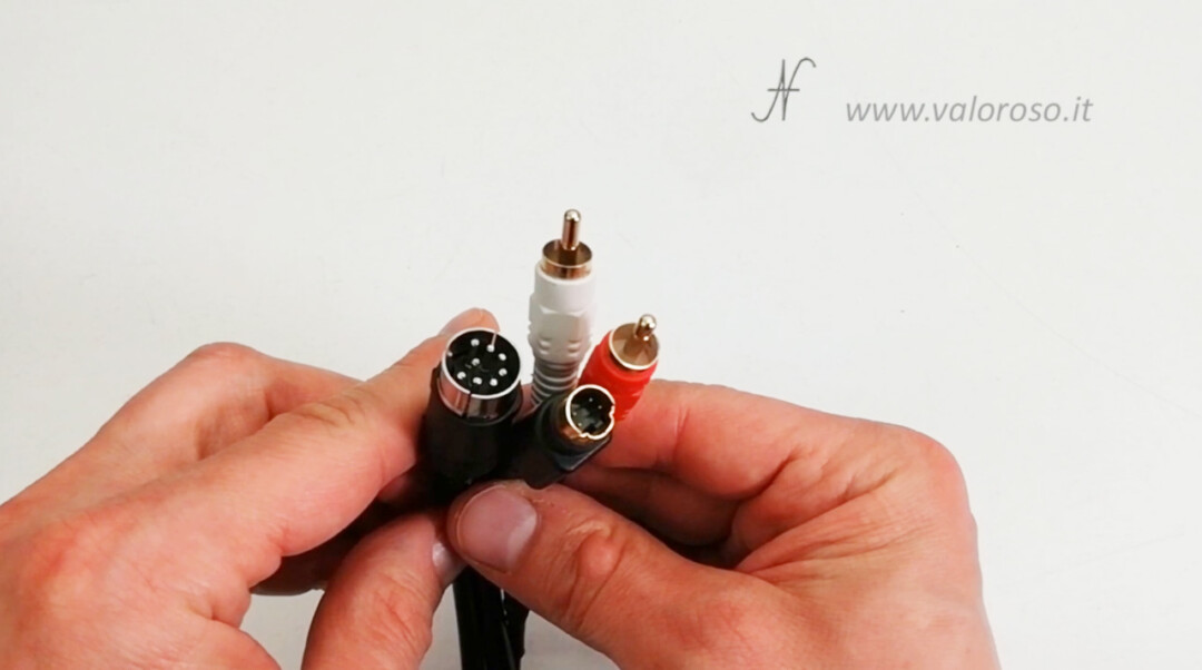
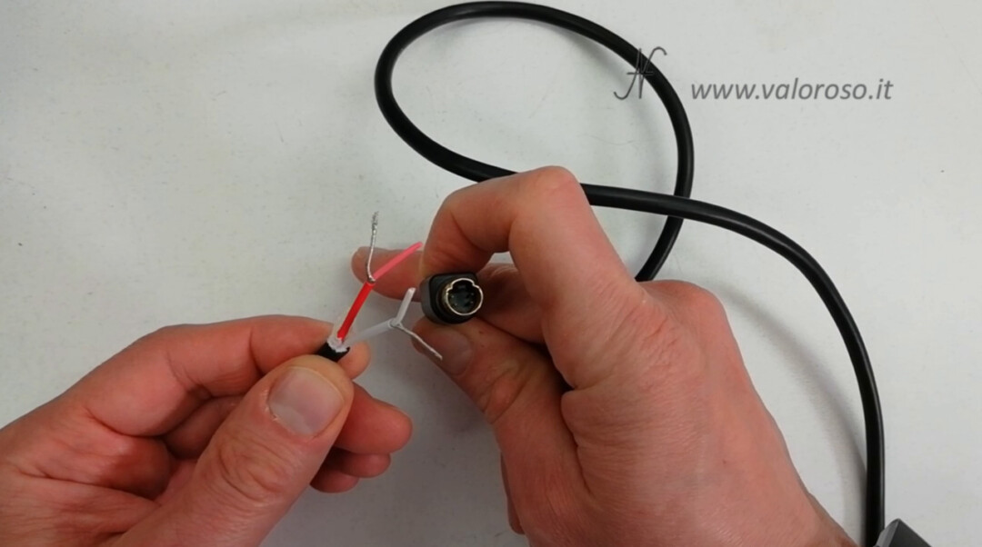
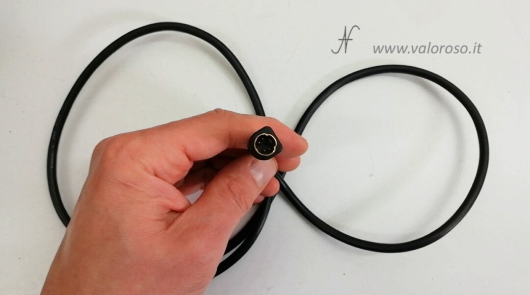
We split the S-Video cable in two. Obviously, each of the two halves must be long enough to connect the Commodore to the monitor.
With the utmost delicacy, we can now strip all the cables, in order to reach the copper inside:
- the SVideo cable, which is made up of two shielded cables, one for luminance and one for chrominance;
- the audio cables of the two RCA connectors;
- the audio cable, mono shielded, which connects the two RCA connectors to the DIN8 connector.
We continue assembling the S-Video cable to improve the Commodore's picture quality. We open the DIN connector. There is a tab to press to remove the shell from the contacts. We insert the two cables (audio and S-Video) into the connector shell. I use a little tape to avoid damaging the stripped copper.
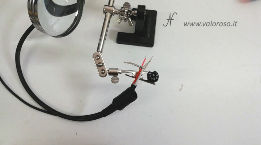
If the cables do not enter easily, you can help yourself with a little lubricant (such as WD40), or with a little soap.
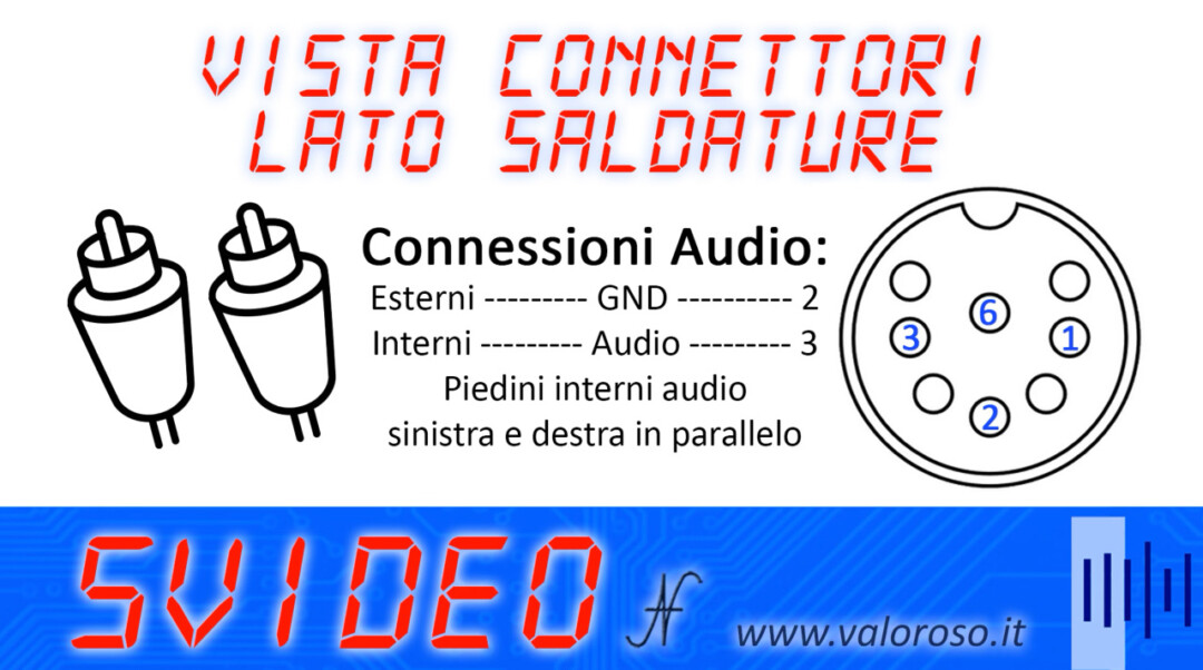
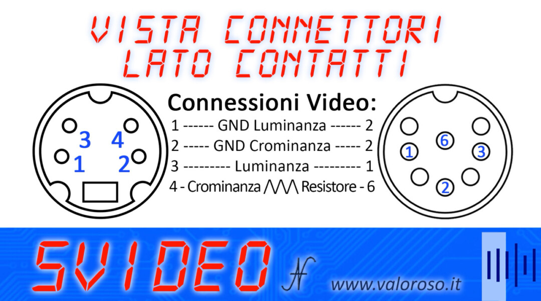
For the connections, you can refer to the following diagrams, which indicate the pinout of the 8-pole DIN video connector contacts (soldering side).
We connect all the masses in parallel to each other (the cable shields, both audio and video), and solder them to pin 2 of the DIN connector.
When soldering the wires to the DIN8 connector, be careful: the wires must not touch the outer metal shell when we will reassemble it.
Relating to the audio section, connect the two RCA plugs in parallel. In this way, the Commodore's mono audio signal is still reproduced by both the left and right speakers of the television. You can refer to the photo that indicates the pinout of the 8-pole DIN video connector contacts (soldering side). We solder the audio signal cable to pin 3 of the 8-pole DIN connector.
We insulate the signal cables well from the shields, so that they do not form short circuits. The heat shrink tubing must be put on before proceeding with the soldering of the wires. When tightening the heat shrink tubing, using a hot air blower or a lighter, be careful not to get too hot, otherwise the cables may melt!
Relating to the video section, the luminance cable must be connected directly to pin 1 of the 8-pole DIN connector.
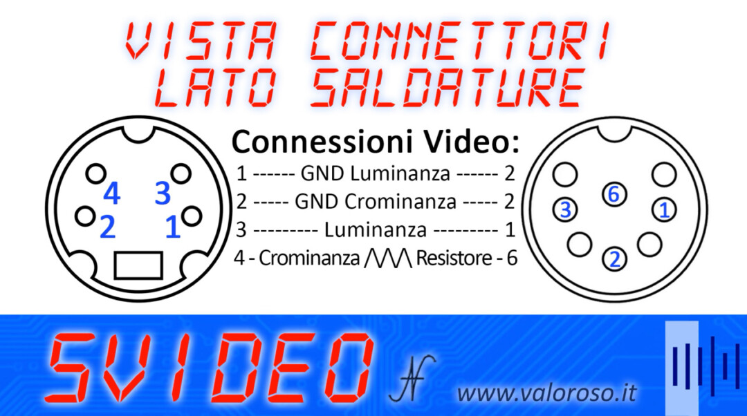
The 75 ohm resistor must be connected in series between pin 6 of the DIN connector (the central one) and the chrominance cable.
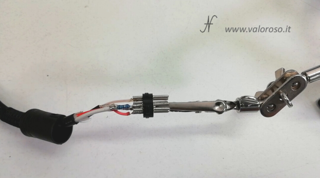
Once all the connections have been completed, with the resistance in series with the chrominance signal too, we can well isolate the cables that could touch the metal shell. Then, we close the connector.
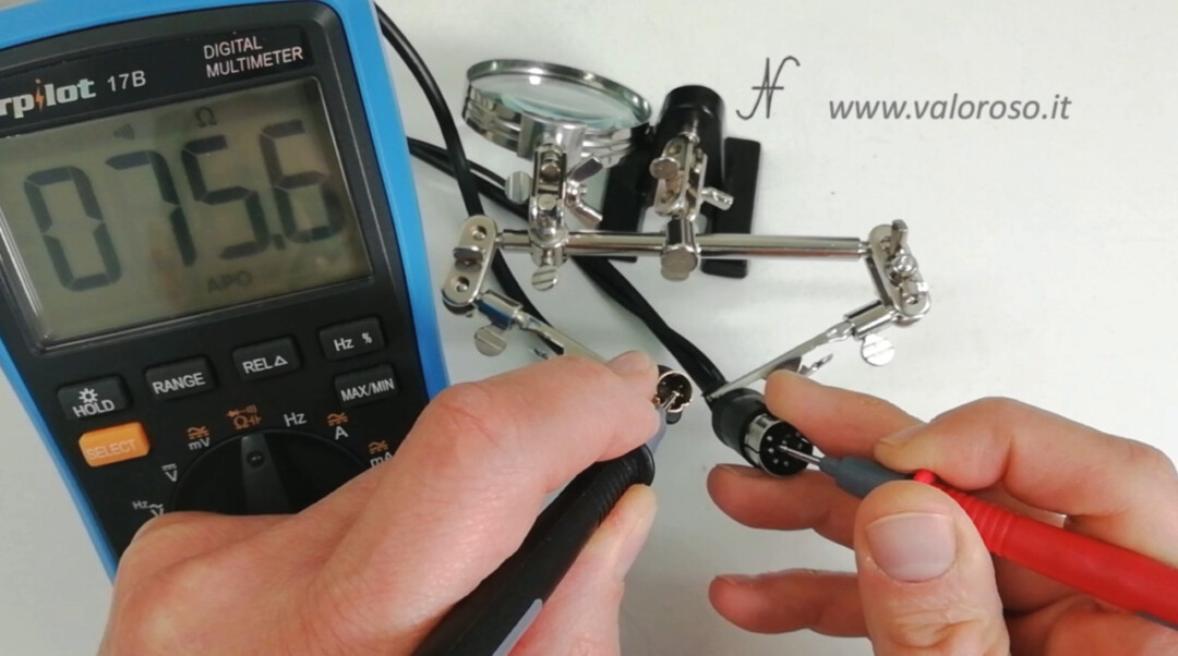
Check the S-Video cable with the tester
After closing the DIN connector, check well with the tester that the connections correspond to the scheme and that no signal is in short circuit with the mass. It is better to try the cable to improve the quality of the Commodore images, before connecting it to the computer.
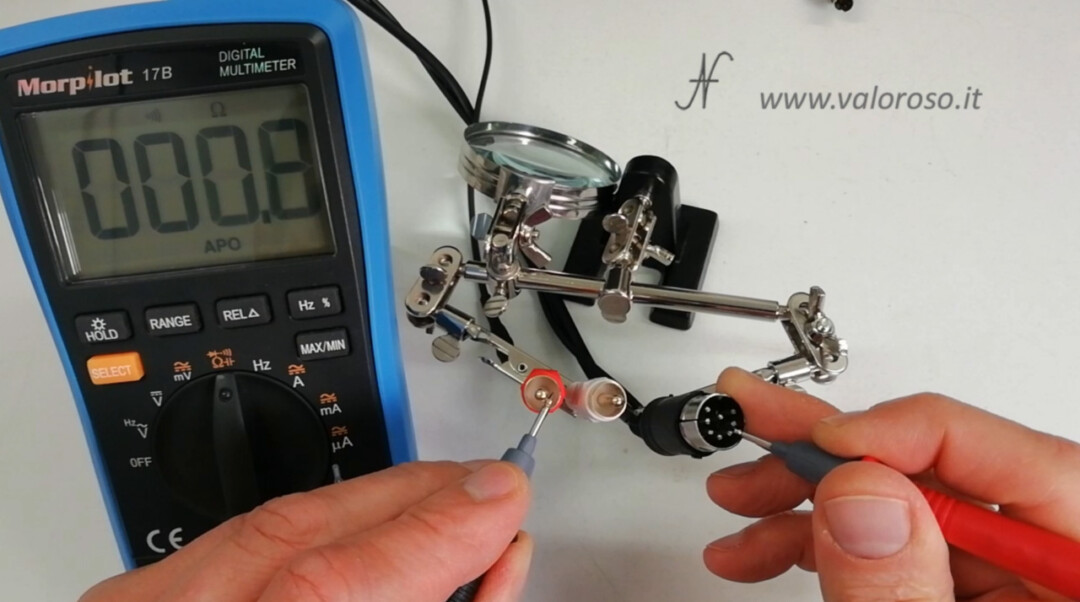
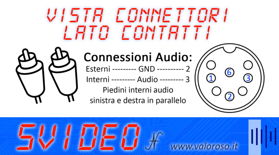
For your convenience, we can check using the connection schemes, ma seen from the side opposite to that of the solder joints: the side of the contacts.
Let's start with testing the audio connections. The ground is pin 2 of the 8-pole DIN connector and connects to the external contact of the two RCA connectors. We also check that the ground is NOT in short circuit with the central contact of the RCA connectors.
Pin 3 of the 8-pole DIN connector is connected to the two center contacts of the RCA audio connectors.
Regarding the test of video signals, pin 2 of the 8-pole DIN connector, the ground, connects to pins 1 and 2 of the SVideo connector and there must be no short circuit with the other two pins of the 4-pole mini DIN connector.
Pin 1 of the 8-pole DIN connector, the luminance, is connected to pin 3 of the SVideo connector and obviously must not be connected to anything else.
The control unit, pin 6 of the 8-pole DIN connector is connected, through the 75 ohm resistor, to pin 4 of the S-Video mini DIN connector. The tester does not find continuity, but measures the resistance value. This pin also must not be short-circuited with other contacts.
You can also check the connections of the Commodore S-Video cable that you may have purchased, especially if you notice any anomalies.
How to connect the Commodore to the TV with the S-Video cable
Perfect: we built the cable to improve the quality of the Commodore images, as per the electrical scheme. We tried it with the tester and therefore we can connect it to the Commodore 128.
Of course, all connections must be made with the computer and television turned off.
The 8-pin DIN connector connects to the Commodore VIDEO output.
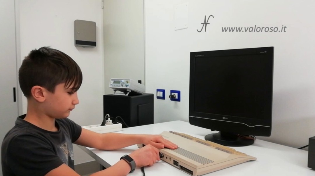
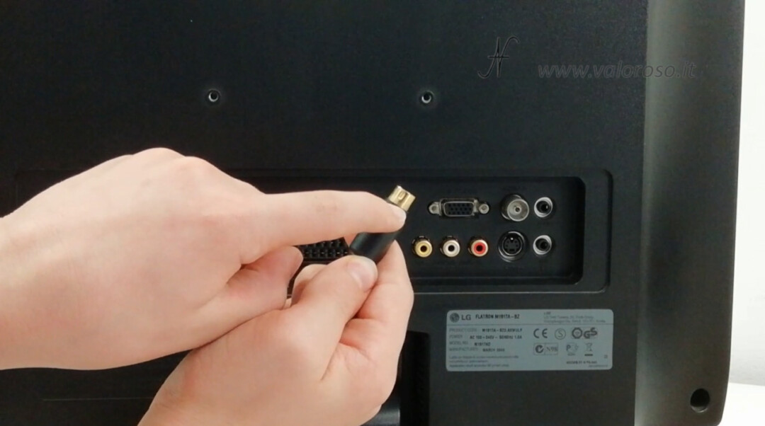
The SVideo connector connects to the corresponding input on the TV: be careful to orient the connectors correctly! Then, we can also connect the two audio RCAs to the TV.
To test the audio, we can load a game, or, on the Commodore 128, we can use the command SOUND, which emits a sound.
SOUND 1,15000,200
Troubleshooting, Commodore poor picture quality
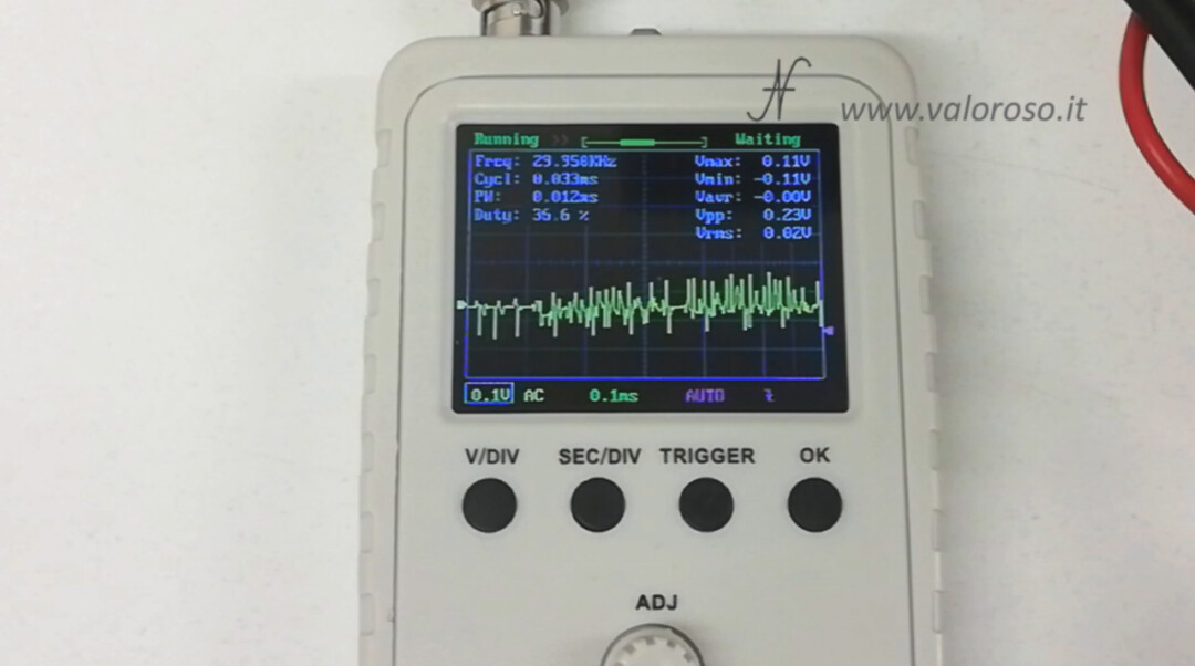
If you see the image with the colors flickering and shaking, it means that the value of the resistance in series with the chroma is wrong (too low), or the resistance has not been mounted at all.
The chrominance signal on the Commodore comes out of just under 1vpp, while the TV accepts signals lower than 0.3vpp. If the value of the resistor is too low, or if the chrominance cable has been connected directly to pin 6 of the 8 -pole DIN video connector, the result will be a shaky image with the colors that flash.
In this image, however, I have not connected the pin 6 of the chroma at all. The Commodore is able to send only the luminance signal to the TV, which does not contain the color information. This is why the image is in black and white. This situation can also occur if the chroma resistance is too high.
With the oscilloscope, we can see that the right resistance value, at least with my monitor, is 75 ohms. The chroma signal comes out of the Commodore at less than 1 Vpp.
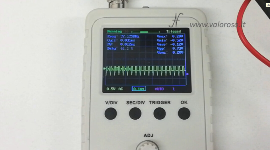
After the resistance, it is reduced to about 0.2 Vpp, corrected for the 0.3Vpp input of the TV.
If, on the other hand, the TV just can't show any image, it means that the luminance signal is interrupted, or your Commodore does not emit this signal.
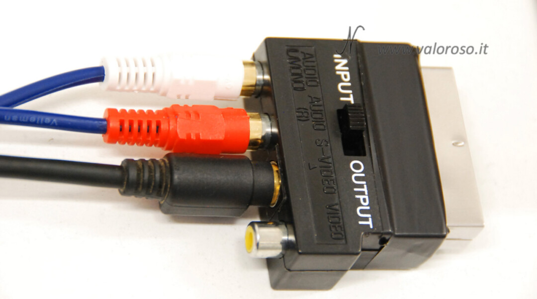
Finally, we can see that the image loses quality if, instead of using the TV's S-Video input, we use the luminance and chrominance inputs present between the pins of the SCART connector.
In my case I used an adapter.
Credits: in the video tutorial, SID music is Alloyrun by Jeroen Tel.
For now, the experiments are finished and I hope this tutorial (with attached video) has been useful to you!
To be notified when I publish more tutorials, experiments and reviews related to retro computers and vintage electronics, I invite you to subscribe to the YouTube channel and activate the notification bell!
I'm not an expert and was wondering if mono cable shielding is absolutely necessary. I have data jack cables available that came with PCs and I wanted to use one of those.
Thank you for the video very well done and for any answer you can give me
Immanuel
Emanuele, shielding is definitely useful to reduce the interference you may hear on the speakers. If the cable is very short, you could try even without it, but I do not recommend it.
Thank you Amedeo.
I tried with an unshielded jack cable from almost 2 meters and I must say that it did not give me sound interference problems.
I used an 82 hom resistor and the result is still very good in my case.
Thanks again.
Thank you so much for the interesting video, but I need clarification: to connect the C64C to a 2020 Samsung LCD TV in which there is the Y/Video entrance and then the PB and the PR how do I have to regulate myself? In addition to not having the scart, this TV does not even have the Value entrance
Thank you! The Y/Pb/Pr input is neither composite, nor SVideo, rather it is a derivative of RGB. It is not directly connectable to the C64. I would opt for an SVideo to HDMI converter (good quality), or I would buy a CRT or LCD TV, 4:3 aspect ratio, with Composite and SVideo input, which probably costs less.
HI. but how the resistance is connected is not understood. in series but if you can explain better. or maybe have two resistors and even better? if I connect the two signals to the resistor in series the two signals go short, I have a composite input on the TV. the two audio cables and then three inputs. I think it's the same as s video? Would you be so kind as to explain to me the connection of the resistance and my composite speech if that's okay too? thanks I always follow you. Well done
and in any case I was wrong, I don't have the composite but the component on the TV, a green input called Y, a blue one called Pb/Cb, a red one called Pr/Cr and two red and white audio inputs. I think it's possible as if I had a video entry. thanks for the replies
Hi, thanks! The resistor goes in series with the chrominance signal. Only to that. It's as if you cut the chroma wire and put the resistor in the middle. Here the change is only for S Video, not for other standards.
You can see it well in the video:
https://www.youtube.com/watch?v=R9y3xiuoRRU
The cable I build in this post is only good for S-Video, not for other standards.