In this video article we talk about how to build a replica of The Final Cartridge III+. Let's see how to get the printed circuit board of the interface on PCBWay, how to solder all electronic components and how to program the EPROM using the inexpensive TL866II Plus programmer.

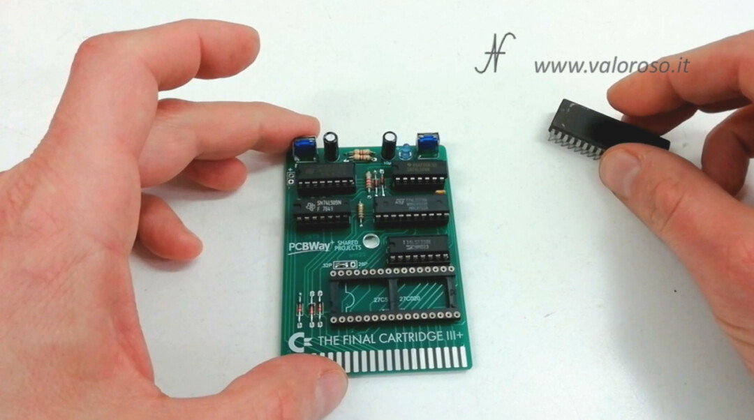
Let's learn how to build a replica of The Final Cartridge III+, with components that you can still find today.
Cos'è The Final Cartridge III+
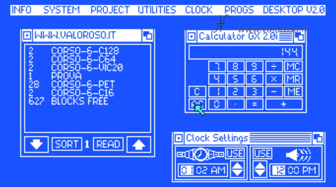
The Final Cartridge III+ is a cartridge that was released in 1987. It connects to the expansion port of the Commodore 64 and 128. The most particular feature is the graphical interface with the arrow pointer, which can be moved via cursor keys, joysticks and, hear hear, also via mouse. The various programs run inside graphical windows, just as they do in modern computer operating systems.
The Final Cartridge III+ offers several features, including a fast loader to load programs and games quickly, as well as a freezer, to freeze a program or game and save its state.
We will only do a short test of the cartridge, just to try if we built it well. I will show all the details of the operation in another tutorial, so I suggest you subscribe to the YouTube channel and activate the notification bell!

Purchase of the components of The Final Cartridge III Plus
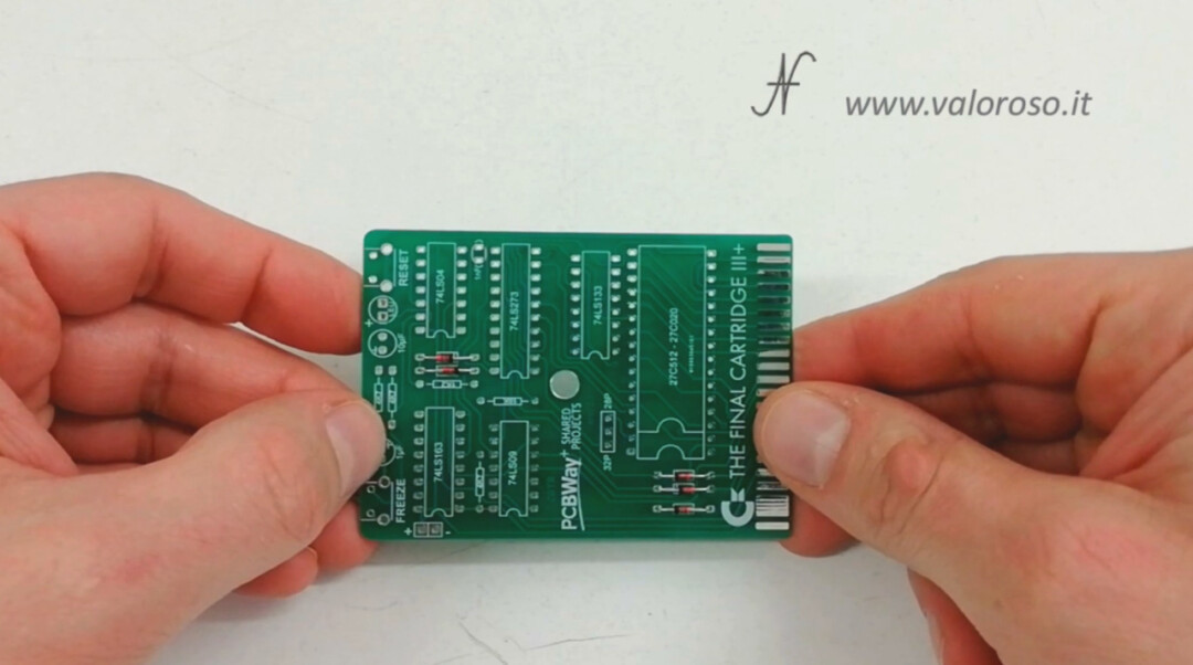
Let's start with the printed circuit board and the list of components. If you search on the site of PCBWay find the printed circuit board replica of The Final Cartridge III+ ready. You will also find the binary files to program the EPROM. On PCBWay you will also find the list of electronic components: they are easy to find. You can buy them online or in an electronics store.
For convenience, report the list of components to buy:
PCB
27C020 (27C2001) DIP32 or 27C512 for plain version
74LS273 DIP20
74LS163 DIP16
74LS133 DIP16
74LS04 DIP14
74LS09 DIP14
DIP32 IC SOCKET
DIP20 IC SOCKET
2pcs. DIP16 IC SOCKET
2pcs. DIP14 IC SOCKET
1nF Capacitor
1μF Capacitor
10μF Capacitor
5pcs. 1N4148 DIODE
1.2K Resistor
18k Resistor
3pcs. 4.7K Resistor
LED
3pin male header with jumper cap (or wire)
2pcs. RIGHT ANGLE TACTILE BUTTON
In the list of components on PCBWay is indicated only one 32-pole socket: that of the EPROM, but I suggest to mount also the other integrated circuits on the socket, for better maintenance of the interface.
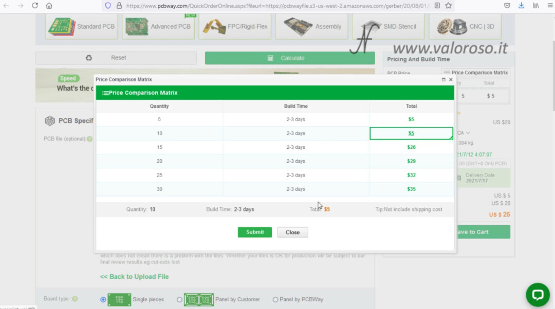
Let's try to simulate the purchase of the printed circuit board on PCBWay. It can be noted that the minimum purchase quantity is 5 pieces, but, if we open the price comparison table, we see how the cost of 10 pieces is identical to that of 5! With regard to transport, shipping costs to Italy vary depending on the courier used, as well as the delivery time.

In my case, I was lucky! In fact, the printed circuit board was donated to me by Stefano Spiacci.
With all the components available, we can start mounting The Final Cartridge III+.
In a Previous Video, I had already explained how to solder the electronic components on the printed circuit board, safely. We saw all the necessary tools, how to choose the temperature of the soldering iron and how to clean the molded after assembly.
How to choose the EPROM of The Final Cartridge III Plus
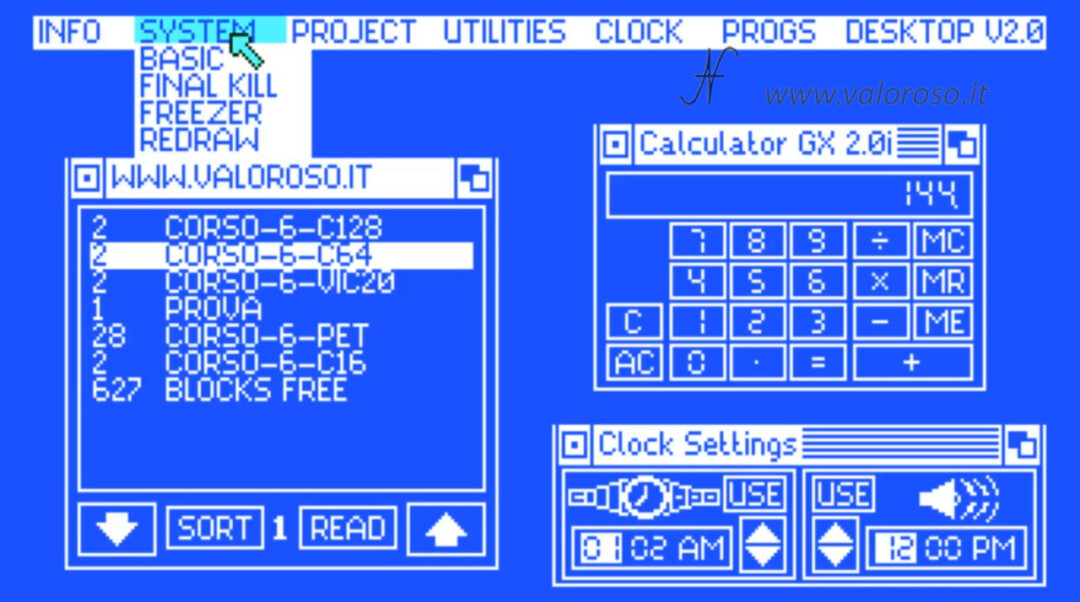
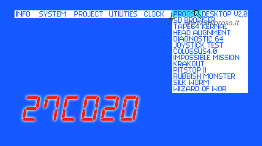
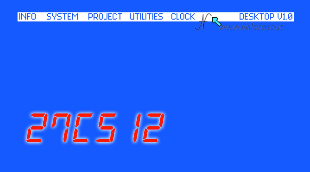
The Final Cartridge III Plus accepts 2 types of EPROM: the 27C020 (equivalent to the 27C2001) 32-pin and the 27C512 28-pin. Being the memory with 32 pins, the 27C020, four times more capacious than the 28-pin one (the 27C512), we will use this. The EPROM 27C020 can also contain applications, which the less capacious EPROM does not have. This is the menu of The Final Cartridge III+ with the 256KB 27C020 EPROM:
Instead, in the menu of The Final Cartridge III+ with the 27C512 64KB EPROM, the additional applications are missing:
Mounting the cartridge, silicon diodes
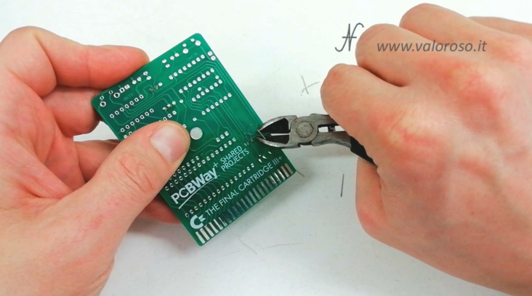
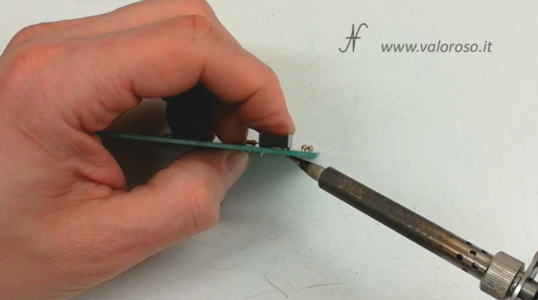
We start the assembly from the lowest components: the 5 silicon diodes 1N4148. Attention that they are polarized components, so you will have to orient the black band (corresponding to the cathode) as indicated on the screen printing of the printed circuit board.
After soldering the diodes, we can cut the leftover of the leading wires with a nipper.
The EPROM type selection jumper
Now, we are comfortable with a rheophore leftover for the bridge. We solder the reophore as if it were a jumper: between the central pin and the one to the left of the selector, in order to make the PCB compatible only with the 32-pin EPROM, the most capacious one. As an alternative to the reophore, you can use a 3-pole pin strip with short-circuit jumper for selecting the type of EPROM.
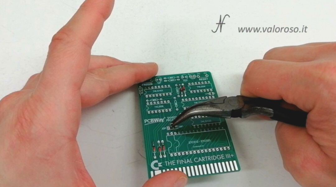
After soldering the jumper, we can cut the leftover of the rheophore.
The resistors
Now let's move on to the assembly of the 5 resistors. On the screen printing of the printed circuit board there are written the values of the resistances to be mounted. We must insert the resistors respecting the correct value. No matter the orientation, but I still prefer to orient the resistors on one side, to improve the aesthetics of the printed circuit board.
When we mount the resistors, but also the other components, we always try to keep them beautiful adherent to the PCB.
After soldering, we cut the leftover of the leading wires.
The sockets of integrated circuits
The time has come for integrated circuit sockets. We insert one at a time, orienting the reference notch as indicated on the silk screen printing of the printed circuit board.
We do not immediately solder all the pins, but only two at opposite ends. This technique allows us to straighten the socket, keeping it tight to the printed circuit board. Pressing the socket towards the PCB while we heat the two pins one at a time, the socket approaches and adheres to the printed circuit board.
Only when the socket is positioned well, we can proceed to solder all the remaining pins. We repeat this operation for all 6 sockets, including the 32-pin one. There are 112 pins to solder!
The choice of the LED of The Final Cartridge III+
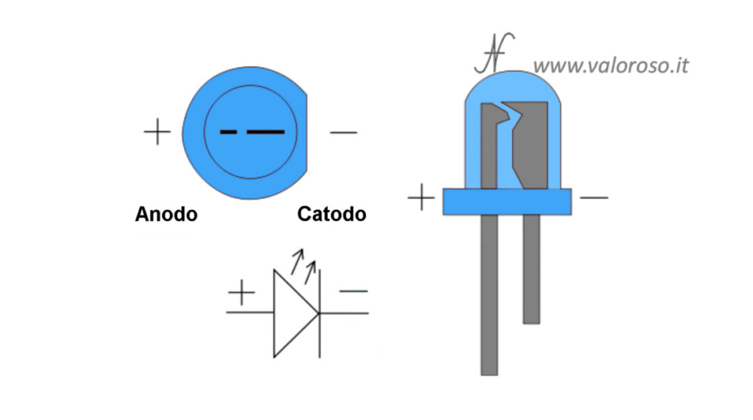
It is the turn of the LED. I bought it blue in color, to rejuvenate the appearance of the cartridge a little. However, you can use it of the color you prefer. The LED is a polarized component and must be mounted following the orientation indicated on the printed circuit board. Theoretically, the shortest terminal of the LED, as well as the flat part of the led body, indicate the negative terminal. If you are in doubt, you can still connect it to a 5V power supply with a 1K ohm resistor in series, and see which way it turns on.
The LED is also a delicate component! Be careful not to stay too much on the leading wires with the welder.
After soldering the LED, we straighten it and cut the leftover of the leading wires with the nipper.
The angled buttons, the choice of the button key
We mount and balance the two angled buttons. I took two buttons with the center be short, because I'm not going to put the cartridge in any container. There are also buttons with longer perno, just to pass through the thickness of a plastic container.
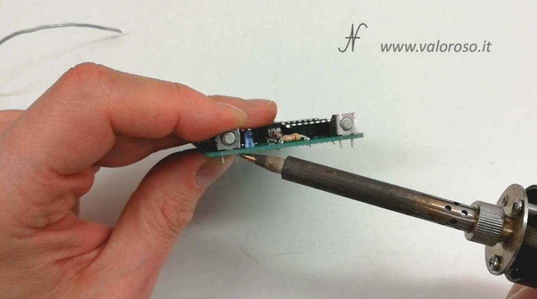
If the terminals of the buttons are too long, after soldering it is advisable to shorten them, to bring them to the level of the leading wires of the other components.
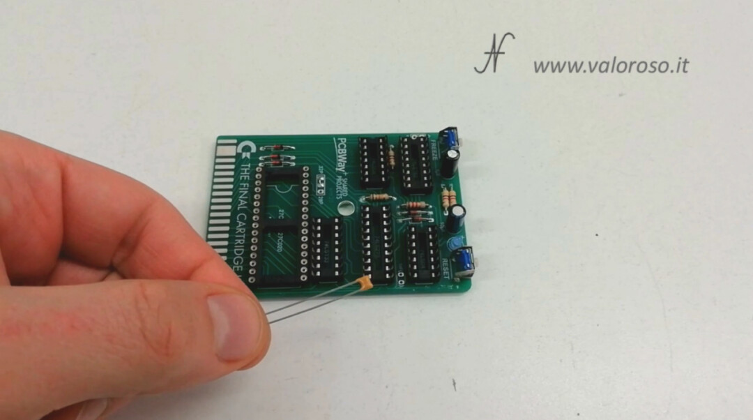
The ceramic capacitor
The ceramic capacitor is not polarized and we can insert it in the verse we prefer. In the video, I mounted it after because ... I had forgotten about his existence! We welcome it and cut the surplus of the reofors.
Electrolytic capacitors
There are now two electrolytic capacitors to be mounted. Unfortunately, I could not find the low-profile ones: the aesthetic impact would have been better. Electrolytic capacitors are polarized components and must be mounted following the indication on the printed circuit board. Typically, on electrolytic capacitors the negative terminal is highlighted. While on the screen printing of the printed circuit board of The Final Cartridge 3 Plus the positive terminal is strangely indicated. The important thing is not to make confusion: the negative terminal of the capacitor must be mounted on the pad opposite to that of the positive!
We're done! The assembly is finished!
First tests of The Final Cartridge III+ with the tester
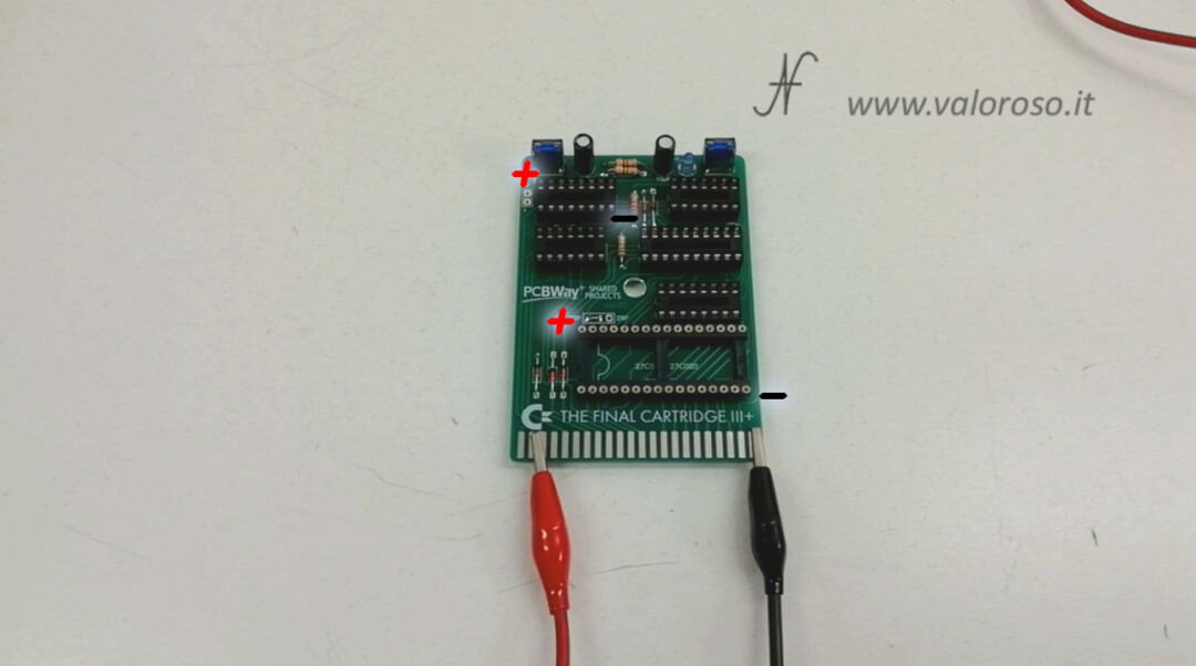
Before inserting the cartridge into the Commodore 64, let's do some tests. First of all, without inserting the integrated, we try to power the 5V cartridge, as the Commodore 64 would do, but through a power supply, in order to verify that there are no short-circuited power tracks. In which case, the power supply would go into protection.
Then, let's verify, with the tester, that the 5V voltage actually reaches the power pins of the various integrated circuits.
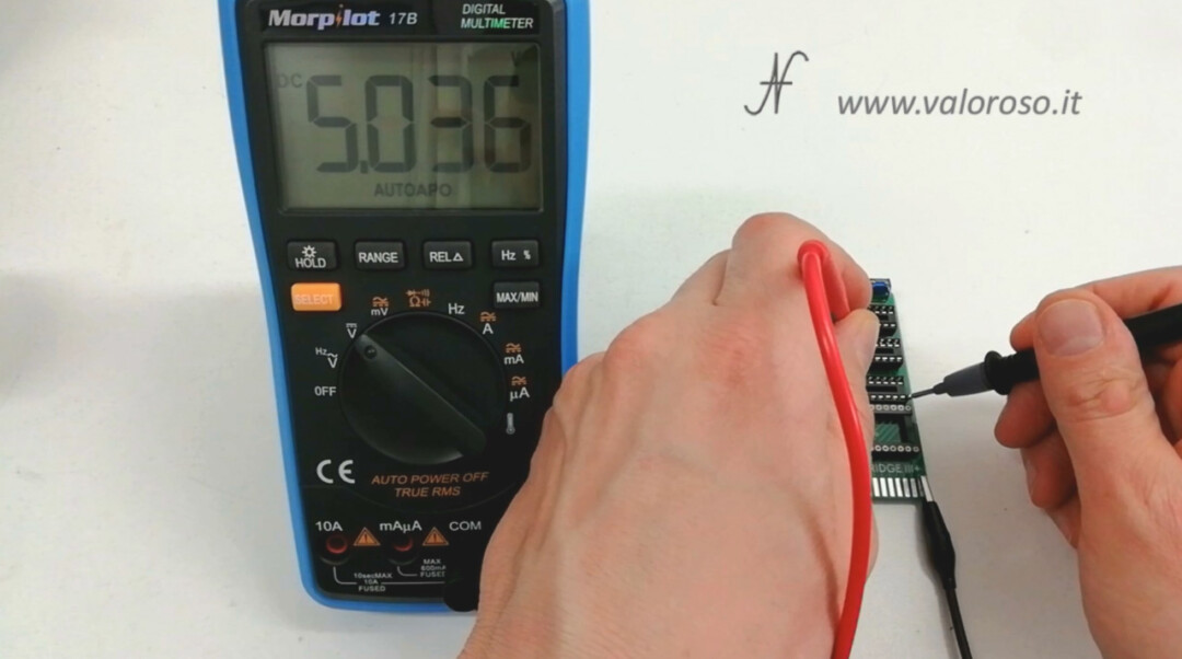
Always without IC inserted, let's try if the LED lights up, applying the 5V before the current limiting resistance.
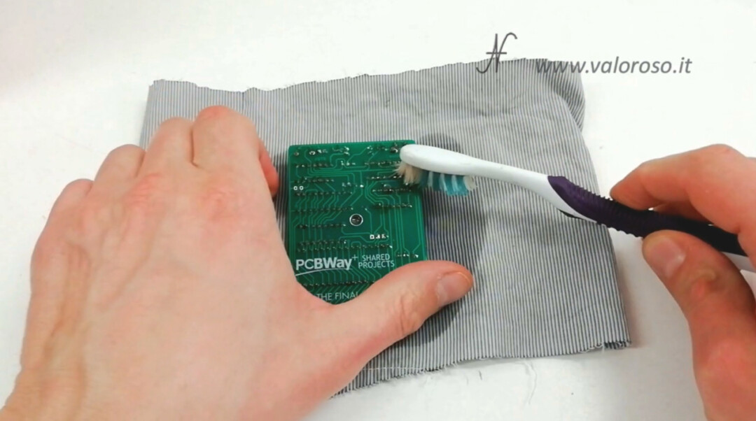
Cleaning the printed circuit board from solder residues
We can proceed to clean the printed circuit board from the flux residues of the solder. We use alcohol and a toothbrush. We can also use a rag that leaves no hair. We repeat the cleaning as many times as necessary, until the printed circuit board is no longer sticky.
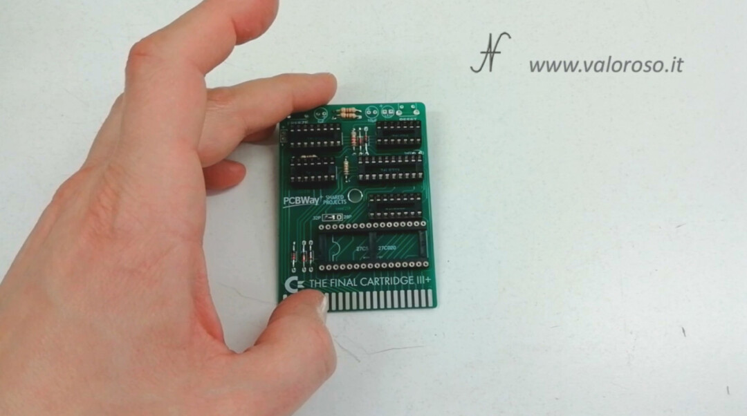
And here, finally, the circuit completed and cleaned!
Inserting integrated circuits into the socket
We insert each integrated circuit into the respective socket. On the silk screen printing of the printed circuit board is clearly indicated the position of the various ICs.
We slightly fold the pins of the integrated circuits so that they enter the contacts of the sockets. Attention also to orientation, indicated by a notch on the integrated circuit, on the socket and on the screen printing of the printed circuit board.
We insert all the integrated circuits, except the EPROM, which we still have to program. As promised, in the next paragraph, I will quickly explain how to program an EPROM.
Program the EPROM with the TL866II Plus programmer
Let's use the compressed file, containing the binaries, that we downloaded before from PCBWay. Inside, in addition to the interface manuals, we also find two folders with the names of the EPROMs. As I explained before, I chose the 27C020 because it has four times more memory than the 27C512: basically there are also applications, which we then find in the menu of The Final Cartridge III +.
We extract the TFC3PLUS_256KB_ROM.BIN file, which we must program in the EPROM.
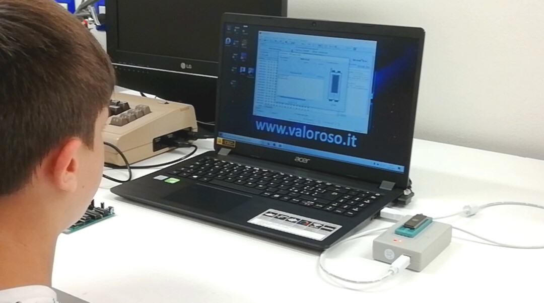
In a future tutorial I will show how to install the XG Programmer programming software, accompanying the TL866II Plus programmer. I will also explain in detail how to use the programmer. Today, we just program the EPROM of The Final Cartridge III+ without too much technical explanation.
We open the XGecu Programmer's software. The TL866II Plus programmer is already connected to the computer via the USB port.
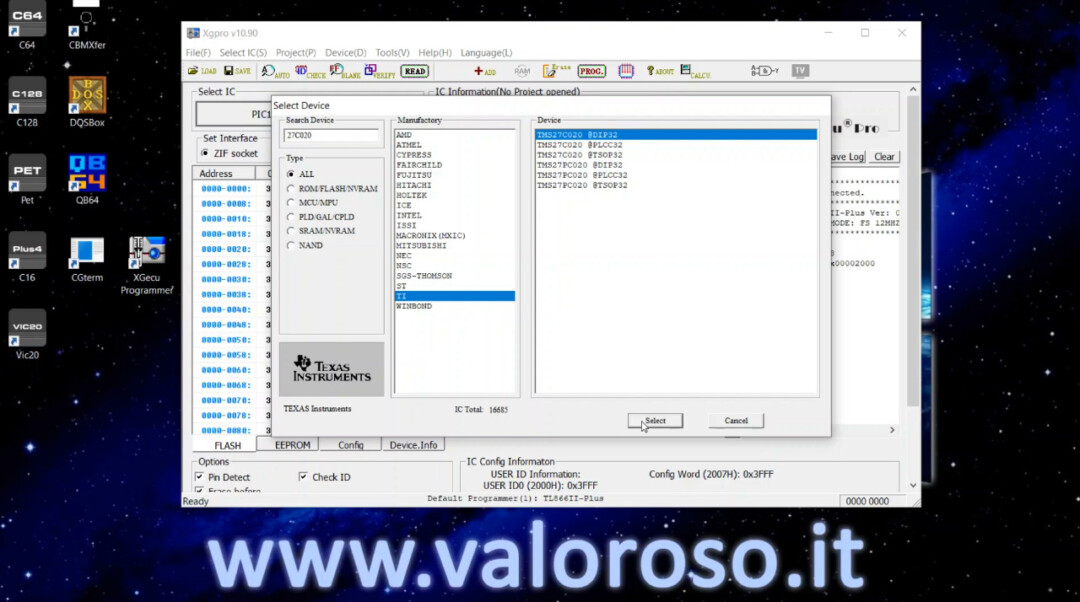
Let's go up Select IC and we choose the EPROM 27C020. There are several manufacturers. Mine is produced by TEXAS INSTRUMENTS, I choose the TMS27C020 with DIP32 container.
Click on the icon LOAD and we choose the TFC3PLUS_256KB_ROM.BIN file, which we downloaded and extracted before. We leave unchanged the settings shown in the window Options.
The binary file loads and we can see its contents in the table.
We leave the standard settings of programming voltage, current, etc...
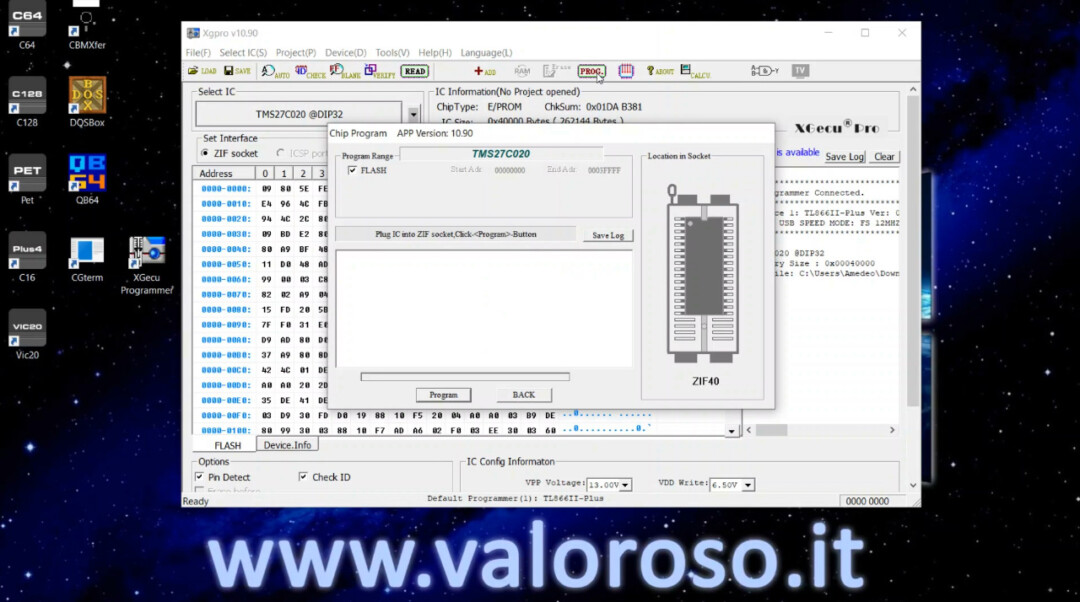
To start programming the EPROM, click on Prog. The software shows us how to place the EPROM on the socket.
We open the programmer's socket and place the EPROM correctly. Obviously the EPROM must be empty. These EPROMs with transparent window can be erased with an ultraviolet lamp.
Be careful to insert the EPROM in the correct direction, indicated by the notch on the body. If everything is fine, we can close the socket and start programming by pressing the button Program.
The programming of the EPROM lasts more than a minute. When it is done, the software performs the verification.
If everything is fine, a message of success is shown.
Installing the EPROM on The Final Cartridge III+
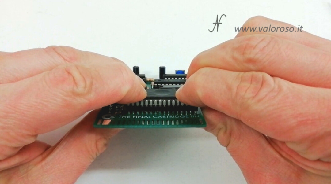
We can cover the window of the EPROM with dark electrical tape, to prevent light from deteriorating the content we have just programmed. We insert the EPROM on the socket of the Interface The Final Cartridge III+, paying attention to the orientation, indicated by the notch on the body of the integrated.
Before pressing the EPROM with energy, also be careful to correctly insert all the pins in the socket contacts. If you do not pay attention, some pins may bend.
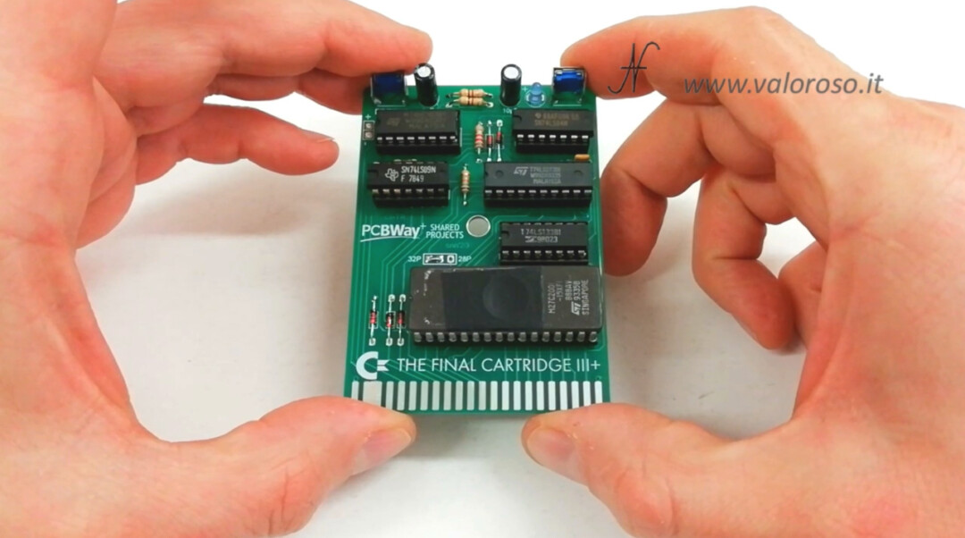
And here is our beautiful interface The Final Cartridge III+ complete and clean! To me, it seems to come very well. What do you think? Let me know in the comments.
The Test of The Final Cartridge III+
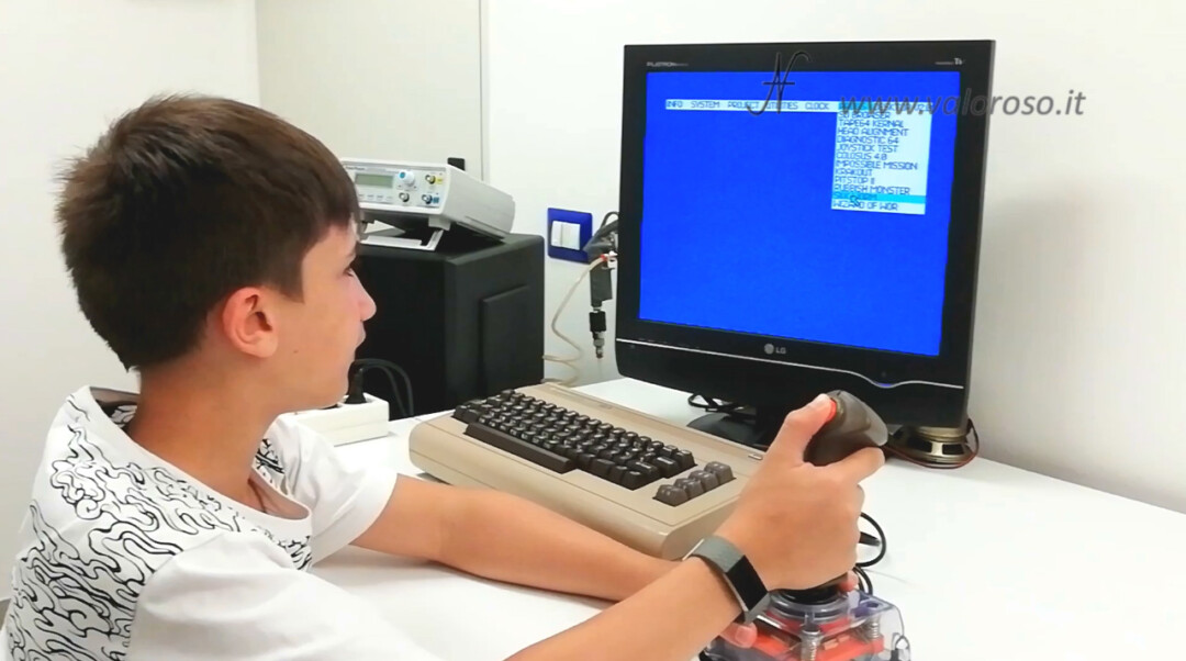
Ok, the time has come! We insert The Final Cartridge III+ into the expansion port of the Commodore 64. Obviously, this must be done when the computer is turned off.
We turn on the computer and, after a few moments, the menu of The Final Cartridge III Plus must appear.
We can quickly try the various menus with the joystick. I will show all the details of how The Final Cartridge III+ works in another tutorial.
Continues...
Curious to analyze all the functions of The Final Cartridge III+?
Credits: in the video tutorial, SID music is Noisy Pillars by Jeroen Tel.
To be notified when I publish more videos, experiments and reviews related to retro computers and vintage electronics, I invite you to subscribe to the YouTube channel and activate the notification bell!
Thank you Amedeo Valoroso
If you mind, the PCBWay order link:
https://www.pcbway.com/project/shareproject/_DIY__FINAL_CARTRIDGE_III__FOR_COMMODORE_64.html
Regards.
Thank you and congratulations for the project!
I’ve recently started to assemble FC III+, and the info you provide on this site has helped me tremendously. Thank you for all of your time and work.
I'm happy my article helped you!