We rebuild the corroded tracks of the printed circuit board and solder the socket of the Paula CSG 8364R7 audio chip: Here is the second episode of the infinite history of the repair and test of the Amiga 500 that I purchased last year.

In the Previous video, I told you about the purchase of this unfortunate Amiga 500 with several accessories. Then, I bought a second power supply, tested and working, which however was not enough to start the computer. We dismantled, piece by piece, all the Amiga 500 and we understood what the damage was: some corroded slopes on the printed circuit board!
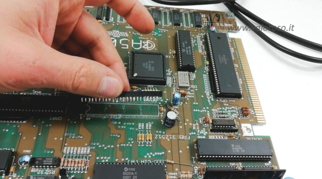
We had unfailed the paula chip clove, also corroded, through the desoldering station ZD-8915. In the first video of this series, I also showed you step by step how to unsolder a socket, or an integrated circuit, using the desoldering iron.
Amiga 500: reconstruction of corroded PCB tracks
We continue the repair from where we left it. We reconstruct the corroded slopes and mount the new socket. Then, let's do the test of the Amiga 500 and see if it starts!
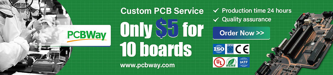
To reconstruct the corroded tracks of the printed circuit board, we recover thin copper wire from a speaker wire.
With this thin wire, we can reconstruct the tracks, passing them in the same position as the original copper. We begin to scratch the solder from the printed circuit board, along the interrupted tracks. The solder protects the copper tracks and we have to remove a part of it in order to solder the new copper wire and rebuild the missing parts of the tracks.
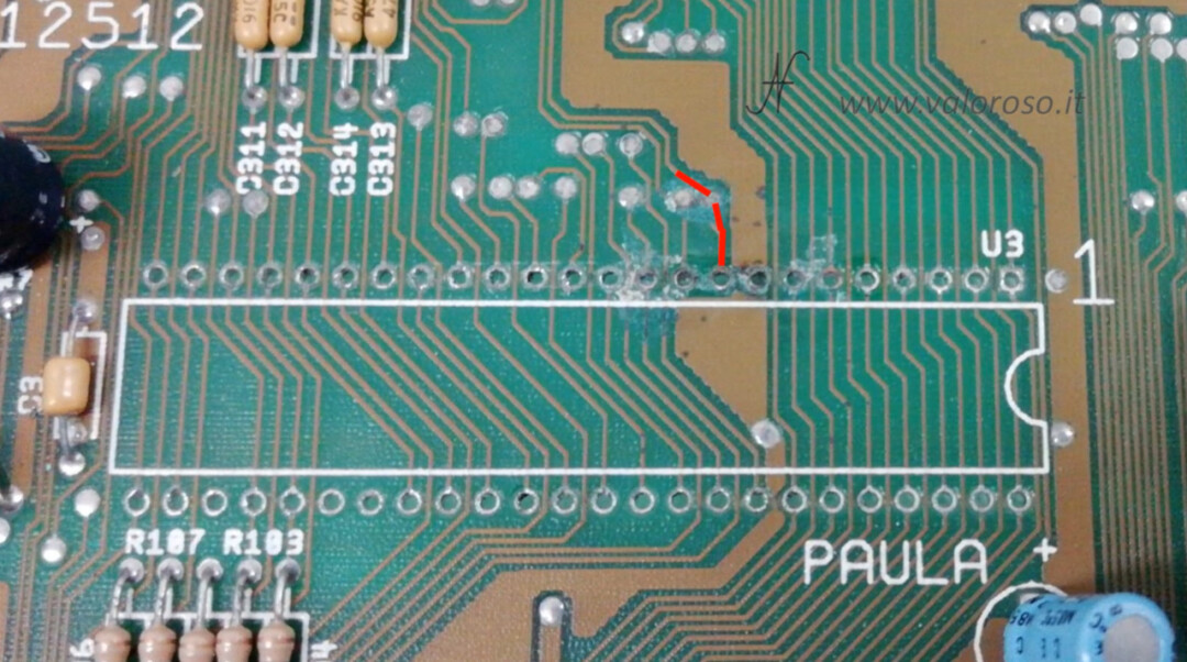
To know where the corroded tracks passed, you can use a photo downloaded from the internet. This photo will allow us to reconstruct the tracks with their original route.
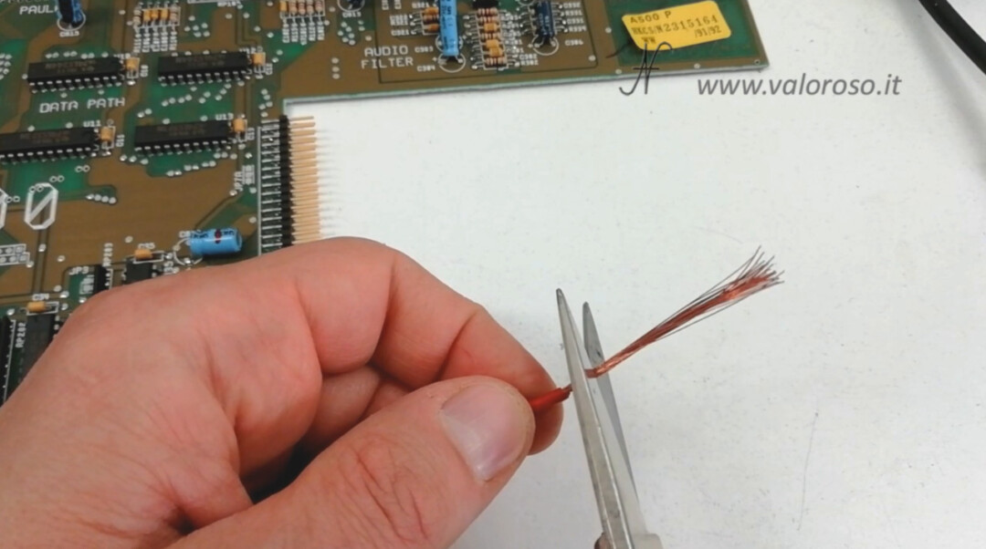
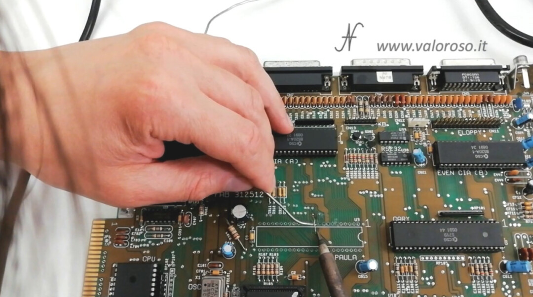
The first track we rebuild is the one on the left. It must start from this pad, it must pass through the Paula CSG 8364R7 integrated circuit pin and it must reach the part of the track that we discovered from the solder.
We solder the copper wire, in order to reconstruct the original track of the PCB.

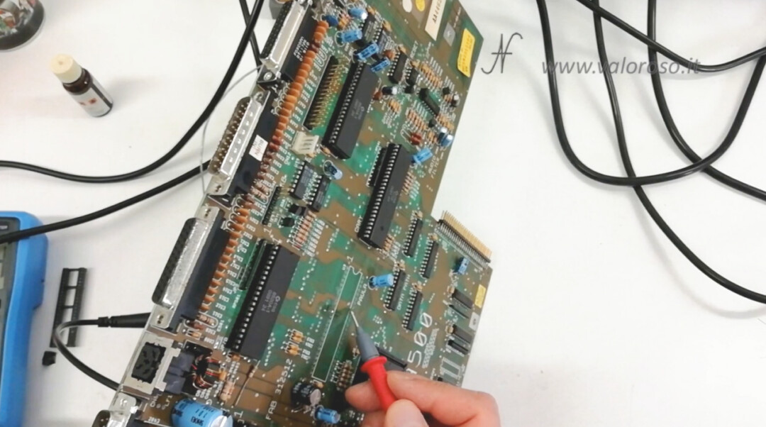
We can now try with the tester: electrical continuity must be found in the path of the reconstructed track (also considering the lower layer of the PCB) and there must be no short circuits with the adjacent tracks and pitches.
And here is the first track rebuilt! We proceed to reconstruct the other corroded tracks. We remove the solder where we will have to solder the copper wire.
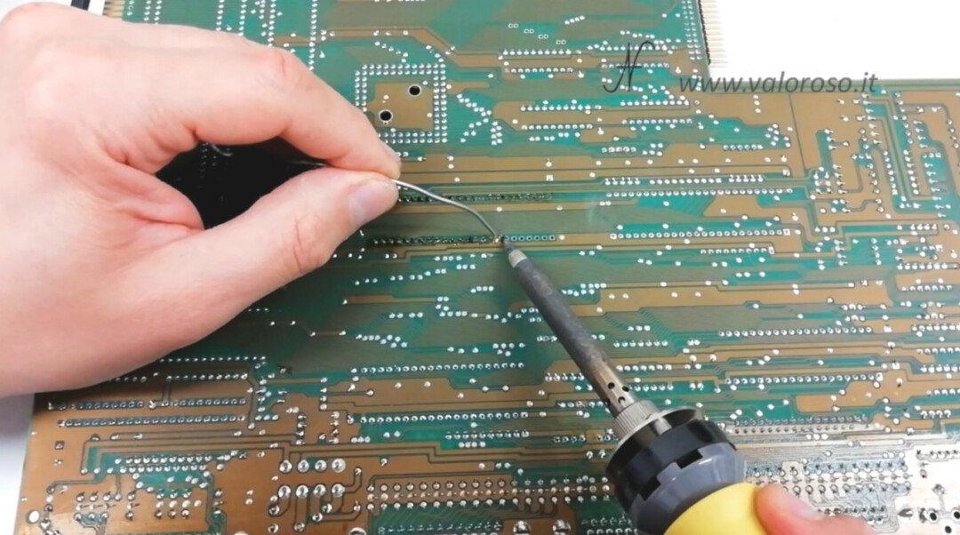
These tracks are more complicated, because the copper from the corroded pad has become unsolderable. We have to vacuum it with the ZD-8915 desoldering station. Along with the station, there are also very thin files, which we can use to clean the hole from oxide residues. It is only necessary to clean the hole, without scratching the metallization of the hole, which allows electrical continuity between the layers of the printed circuit board.
Well, the pitches are now open and we can rebuild the tracks.

We use two copper wires, because the track is corroded on both sides with respect to the pad. Starting from the pad, we reconstruct the track. We first welcome the copper wire on the lower side of the printed, then reconstruct the shape of the track. After applying a little flusting to facilitate the soldering, we can proceed to stagnate the copper.
If you plug the hole in a pin of the socket, don't worry! You can always free it using the solder sucker or the desoldering iron.
The second track is also rebuilt and we can test with the tester that there is indeed electrical continuity. We test the continuity between the two layers and also that there are no short circuits between adjacent tracks.
We cut the excess of copper from the lower layer and proceed to reconstruct the third damaged track of the Amiga 500.
To rebuild the third track, we proceed as for the second: we start from the pad that we have freed and reconstruct the shape of the track on both sides. Then we can weld.
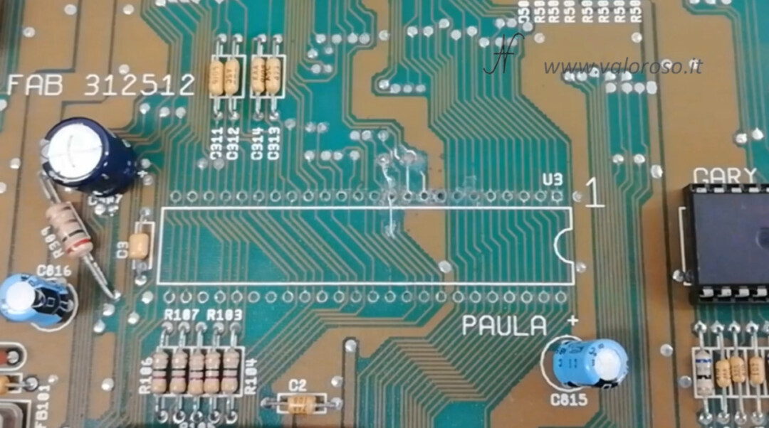
Finally, here are the three reconstructed tracks!
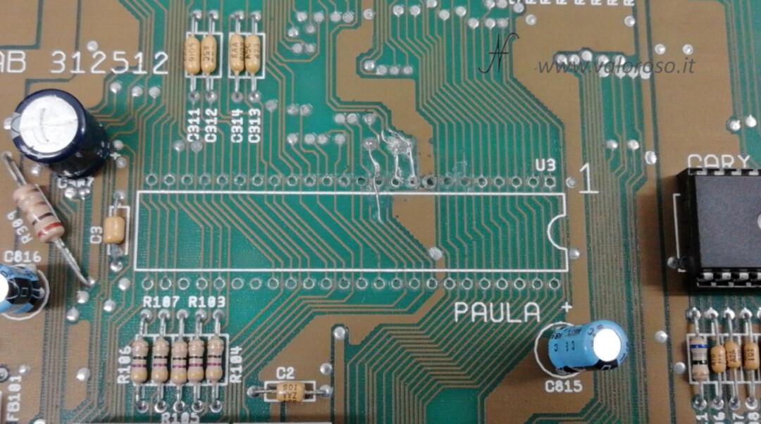
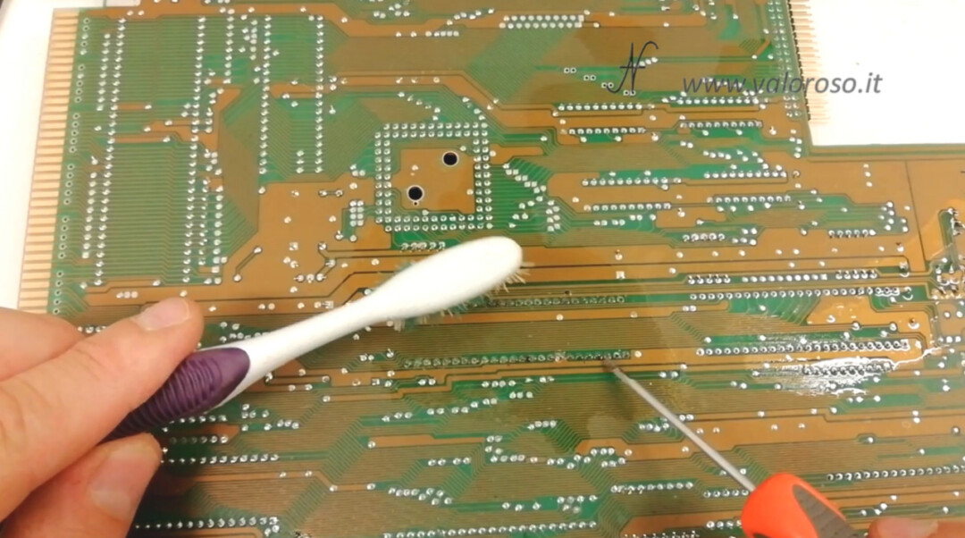
We proceed to clean the treated area, with a little alcohol and a toothbrush. We also use a subtle screwdriver to remove the more tenacious flow bows. During this operation, you have to be delicate, in order not to further scratch the printed circuit board. We shorten the copper surplus from the lower layer of the printed circuit board and ... we still try everything again with the tester!
Amiga 500: solder the new socket of the Paula CSG 8364R7 chip
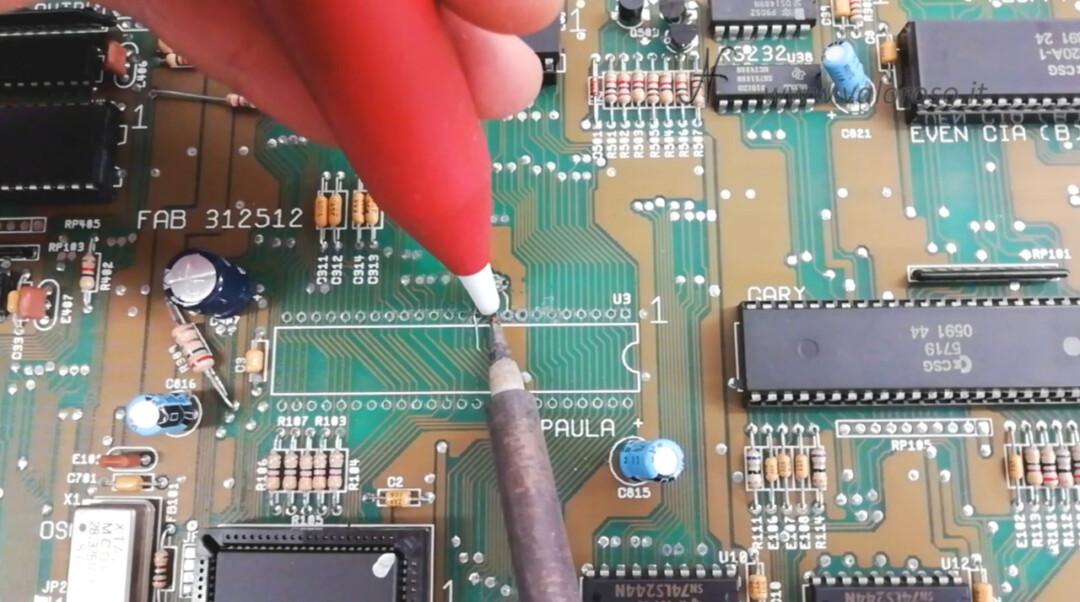
We can now pay the new paula chip clove. Unfortunately I did not find a 48 pin cup. In this case, we use two 24 pin, mounted one after the other.
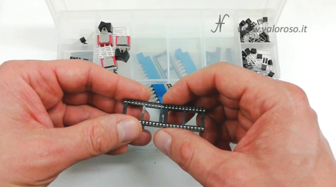
We place the two sockets following the correct orientation, indicated by the screen printing of the printed circuit board.
We apply a little flush to facilitate solder joints. Initially we only welcome two cines per socket, to the opposite corners. Then, we straighten the sockets, in order to keep them beautiful adhering to the printed circuit board. Finally, we can proceed to solder all the pins of the socket.
After soldering, we clean the printed circuit board of flux residues. We use alcohol, a toothbrush and a thin screwdriver for the most stubborn residues. You have to be gentle so as not to scratch the printed circuit board.
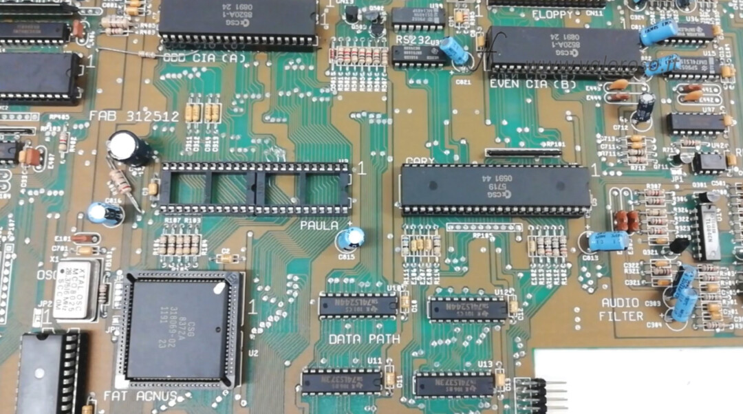
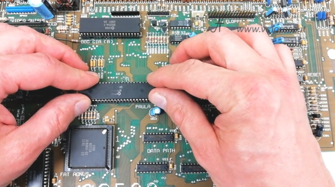
Finally, we reapply the Paula CSG 8364R7 chip on the new socket. Be careful to orient it in the correct direction, indicated by the notch on the body of the integrated circuit.
Test of the Amiga 500
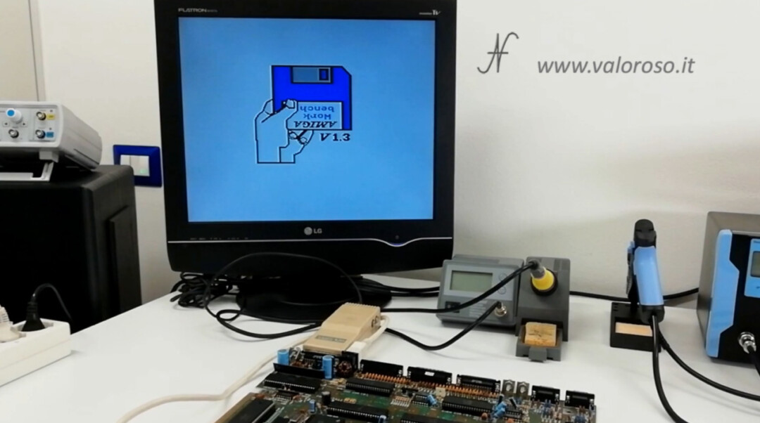
The time has come ... we can do the test of the Amiga 500 and see if it starts or if there is anything else to repair.
For now, we do not reassemble the printed circuit board inside the plastic case. We try it so, open. We connect the power connector and the Commodore Amiga 520 video modulator. The test of the Amiga 500, fortunately, gave a positive result! After some waiting, the computer started!
We can connect the keyboard and the floppy disk drive.
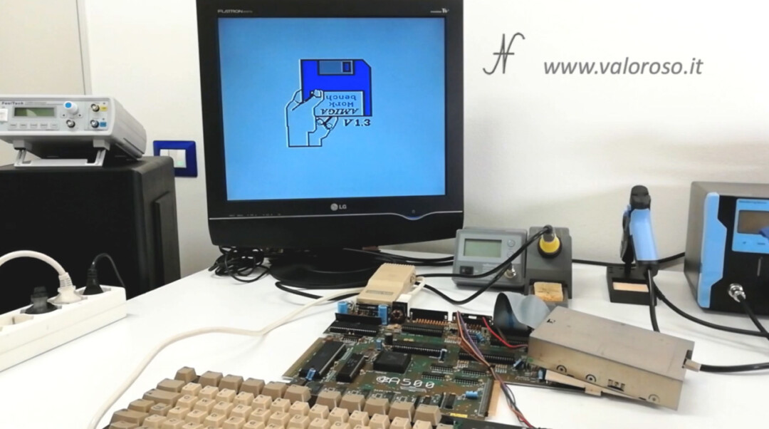
Let's try to upload a disk ...
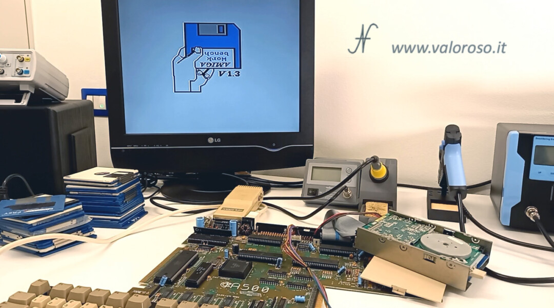
Unfortunately, the sound of the drive is not reassuring. The games are not charged. Obviously ... the drive is also to be fixed. The issue of the drive worries me less, as I wanted to replace it with a gotek to load programs and games via USB pen drive.
Continues...
Well, guys! We reconstructed the three corroded tracks of the printed circuit board and we did two other tests of the Amiga 500: I am happy that the motherboard started, even if we have not yet managed to load a game!
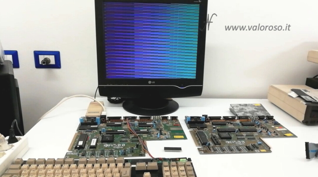
I start to anticipate that I bought a spare motherboard for the Amiga 500, also to compare the results of the tests that I will do. I also bought the diagrom: a diagnostic for the Amiga, which will allow me to find out if the motherboard we have just repaired works at 100%.
Then, I ordered the Gotek to replace the floppy disk drive. There will be surprises!
To be notified when I publish the other videos of the repair and test of the Amiga 500, and also the other videos relating to the back computer and vintage electronics, I invite you to subscribe to the YouTube channel and activate the notifications bell!