Today I begin to tell you the never-ending story of Repair of the Amiga 500 which I purchased last year and which I hoped to be able to use quickly!

Purchase of the Amiga 500
I found an interesting advertisement on Facebook Marketplace. According to the seller, the computer had been stored in the cellar years ago.
The Amiga 500 had not been tested with television, but the green power light was still on. The price was very good and, above all, the computer had many accessories that interested me, so I bought it.
After a few days, the package with the Amiga 500 was delivered to my home!
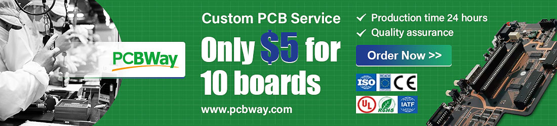
Inside, there was the Amiga 500, its power supply, some joysticks, the Commodore Amiga 520 video modulator, a mouse and diskettes.
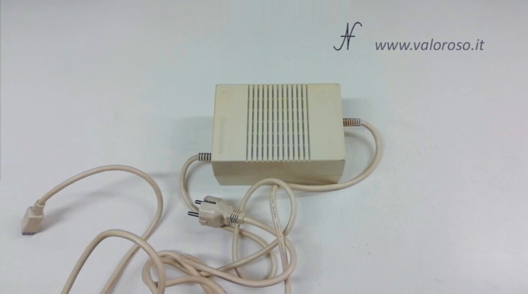
Unfortunately, the test run did not go well. The power supply could not deliver a stable voltage, so the computer turned on and off continuously. In addition, the television screen always remained black. Looking at the power supply carefully, it was slightly swollen.
So I decided to put the Amiga 500 away in a piece of furniture and I haven't thought about it for a few months.
Purchase and test of the power supply for the Amiga 500
Only in April 2021 did I get an eye on the insertion of a power supply for the Amiga. The price was interesting and the power supply was tested, so I bought it.
I had made a video article that explains how to test the voltages of a power supply before connecting it to the computer. I suggest you consult it.

I immediately tried the new power supply, disconnected from the computer, and the voltages were satisfactory.
If you also want to test the voltage of a power supply, be very careful not to cause short circuits, perhaps by touching two pins of the connector with the same test lead, or by touching the outer metal of the connector.
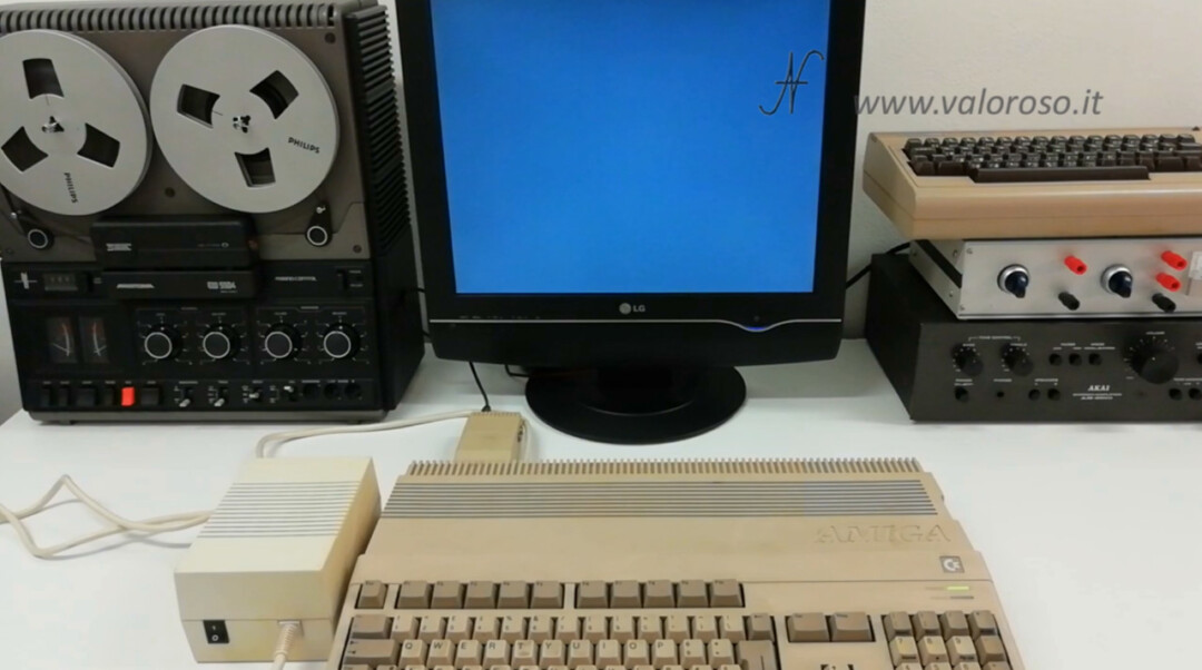
Connect the Amiga 500 to the TV
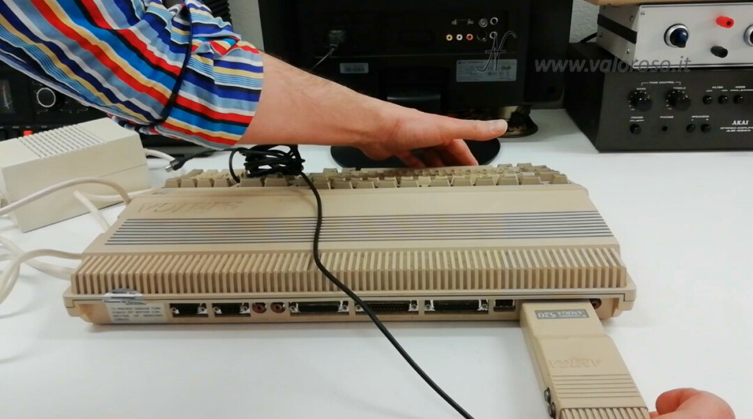
With the new power supply, we could test the computer! I connected the Commodore Amiga 520 audio-video modulator to the computer. Then, I also plugged in the new power supply.
To view the images of the Amiga 500, you need to set the TV to analogue channel 36.
Unfortunately, even when testing with the new power supply, the television screen always remained black.
This attempt also went wrong: unfortunately the Amiga did not start. The green power led returned an error code and the screen remained black.
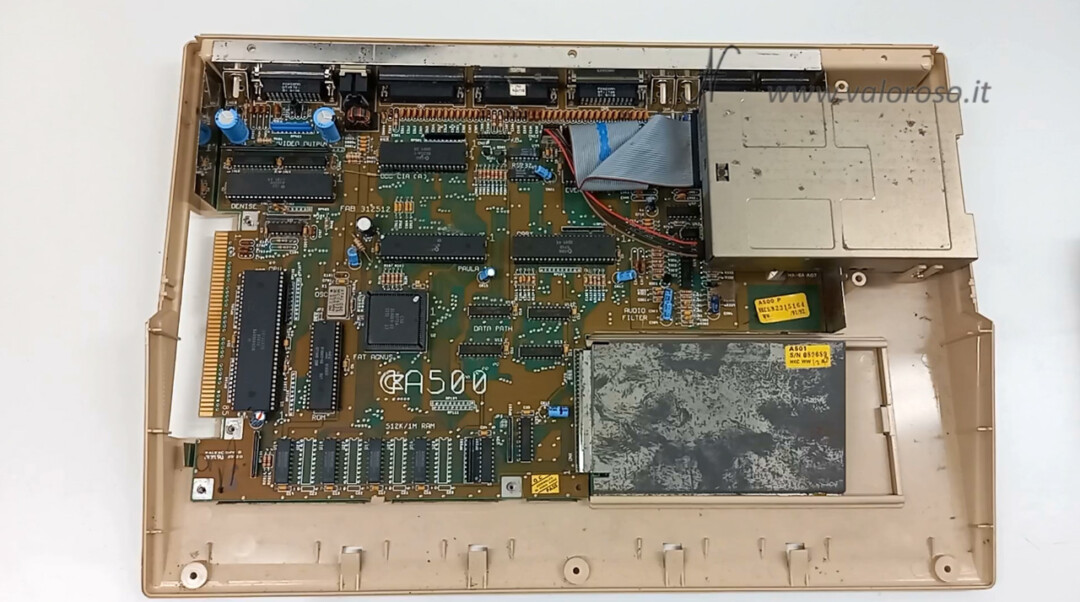
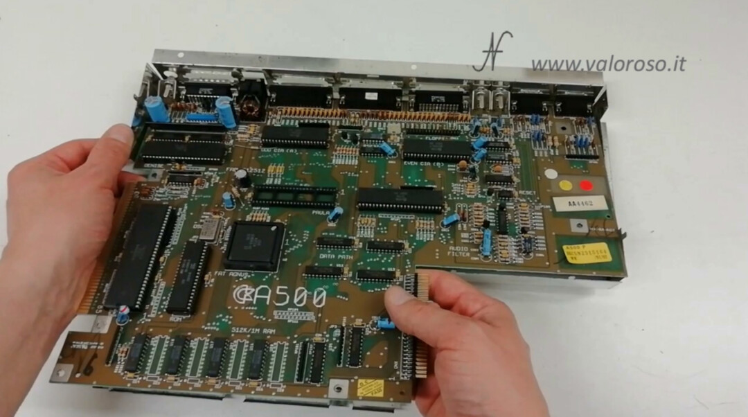
Start of the repair of the Amiga A500: we disassemble the computer
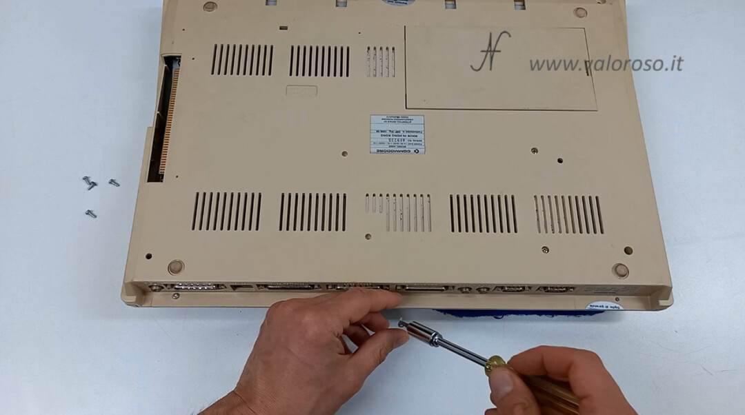
Finally, I decided to start the repair of the Amiga 500. Let's open it to look at the interior.
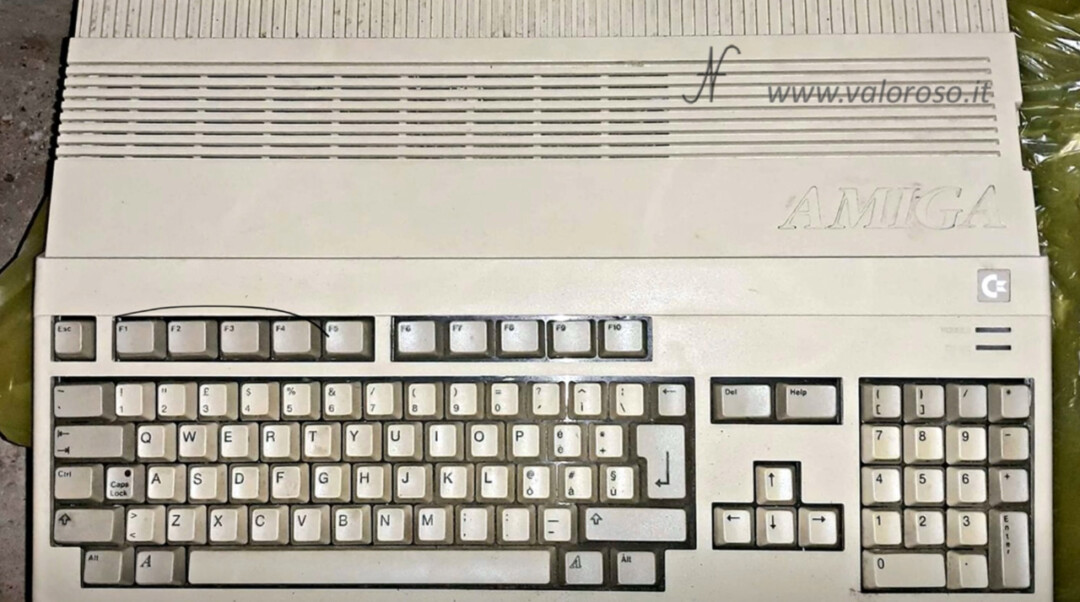
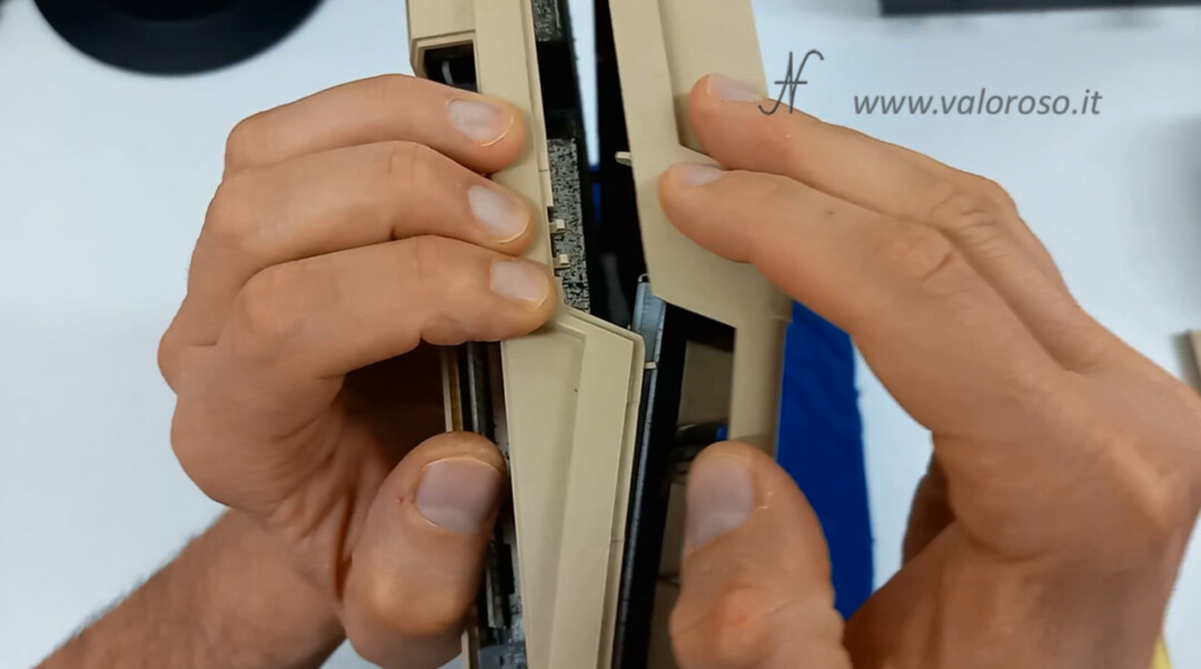
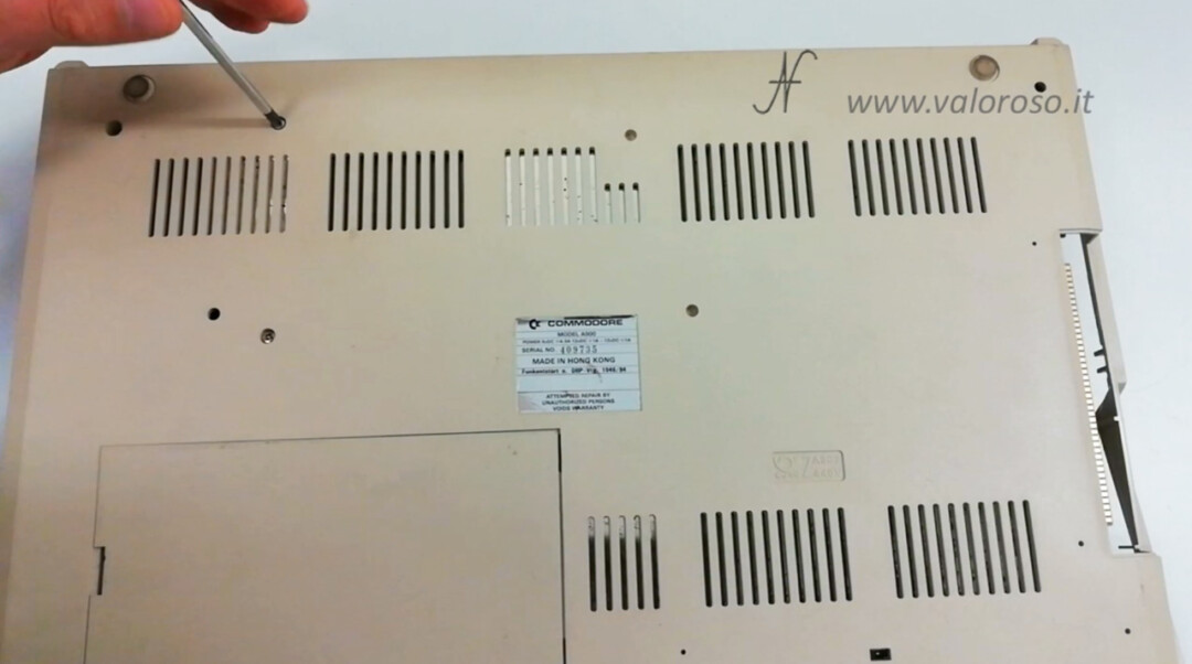
To open the Amiga A500, you need to unscrew the 6 Torx screws located at the bottom of the case. Three are front, under the keyboard. The other 3 are in the back.
When you have unscrewed the screws, you need to separate the two parts of the computer case, being careful not to strain the delicate side tabs. On the side of the case, by applying a little pressure on the lower shell, the tabs are released. This operation must be carried out on both sides of the Amiga 500.
And here's the inside of the Amiga A500! It is quite horrid. There is rust and dust everywhere.
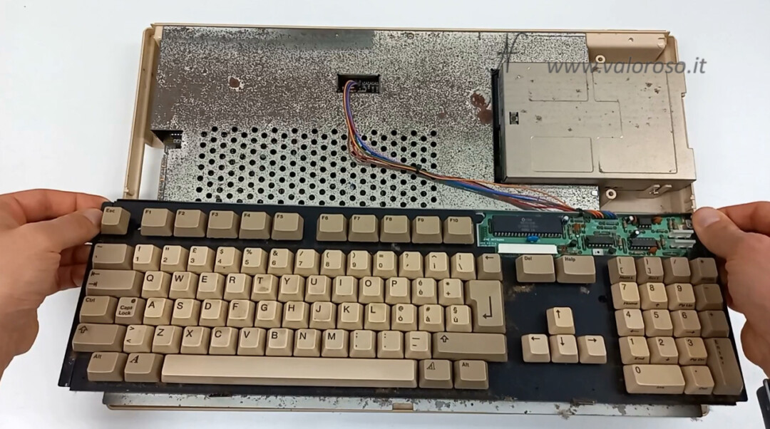
We remove the keyboard. It is only supported by interlocking. You have to disconnect the connector and lift it.
Now is the time to remove the upper metal screen. There are some Torx screws to unscrew.
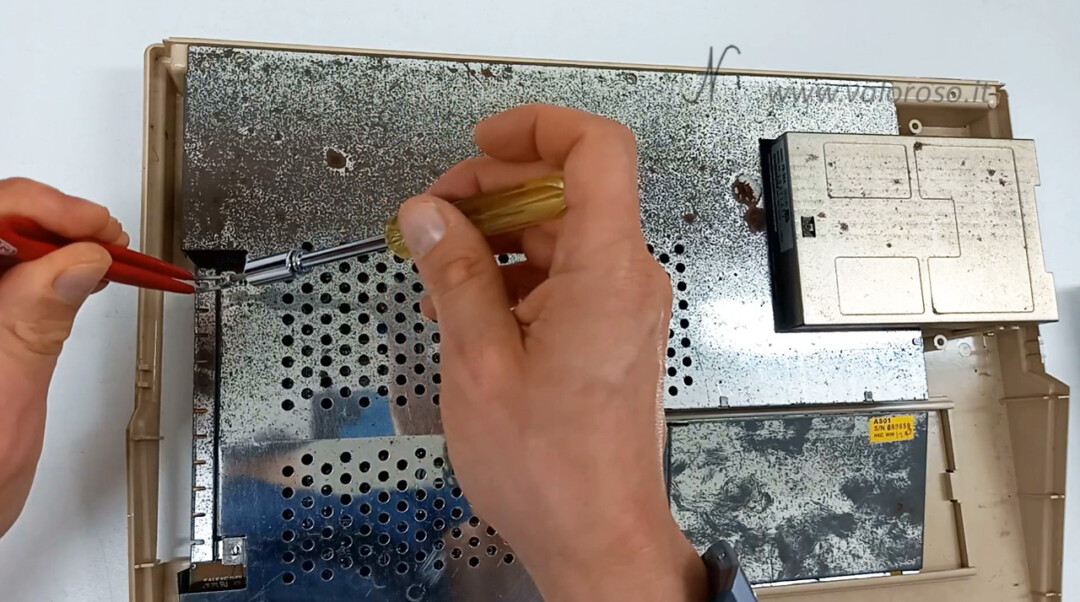
In addition to the screws, you must also lift the tabs that hold the upper metal shield to the lower one. We lift them with a screwdriver and straighten them with pliers.
The tabs are located both in the lower right of the metal shield, and in the upper left.
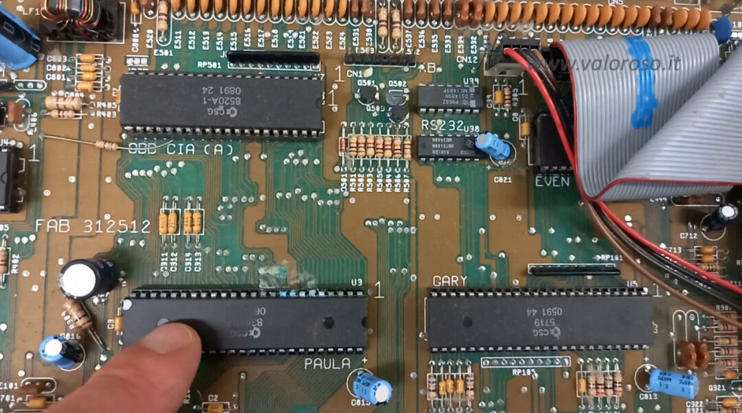
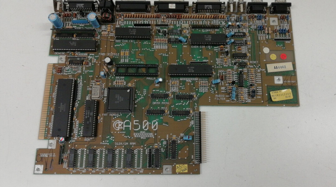
We have finally reached the electronic board and… here's what's wrong! There are corroded tracks near the Paula chip, which is the Amiga 500's audio chip.
To facilitate the repair of the Amiga 500, sprinkle the motherboard. We can use a toothbrush or brush.
Then, let's give a gentle blow with the compressor. I prefer to go out of the laboratory, so as not to dirty everything. While we're at it, let's dust off the keyboard too.
Corrosion of the printed circuit board of the Amiga 500
Let's go back to the main problem of repairing the Amiga 500: the corrosion of the printed circuit board!
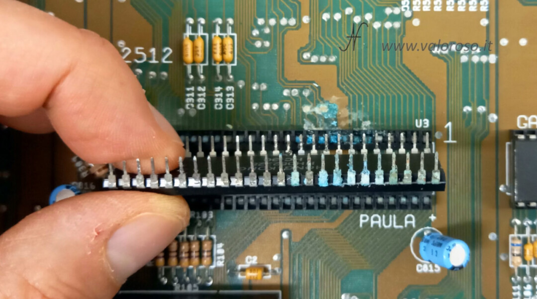
From the Amiga 500's motherboard, I remove the Paula audio chip, an 8364R7.
Corrosion of the printed circuit board is now much more evident. Let's try to remove the oxide with alcohol and contact flux. We can also help with a toothbrush.
Now, after drying the alcohol and the flux, the corroded tracks of the printed circuit board are clearly visible.
Even the Paula chip, the CSG 8364R7, is a bit oxidized. We remove the oxide with a little alcohol, deoxidizer, and fine sandpaper.
In the next video article, we will continue the repair of the Amiga 500 and try to reconstruct the printed circuit board tracks that have been corroded. To work better, let's start removing the printed circuit board from the plastic case.
Remove the Amiga 500 floppy drive
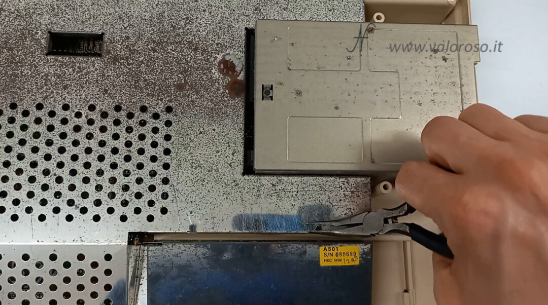
Let's first remove the floppy disk drive. It is necessary to unscrew a lateral screw and three lower ones.
Then, we disconnect the flat data cable and the power cable.
At this point, the floppy disk drive is removed smoothly.
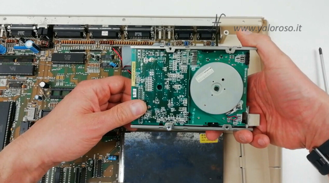
One of the lower screws remained screwed into the turret that holds the floppy disk drive. We have to unscrew it, otherwise the motherboard cannot be extracted.
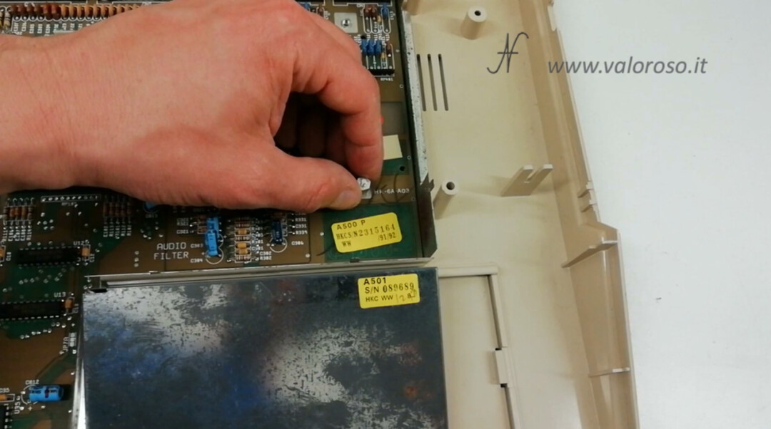
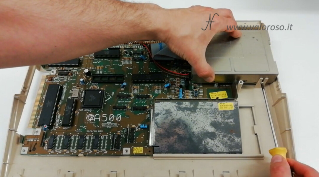
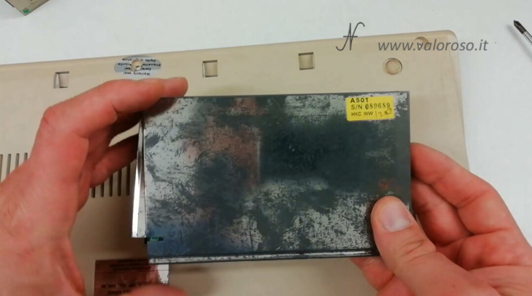
Remove the Amiga 501 expansion card from the Commodore A500
We also remove this expansion card: it is a RAM expansion (Amiga 501) for the Amiga 500. The expansion card is accessible from the lower counter of the Amiga 500. With the help of a screwdriver, we open the door and slide the expansion until it is freed.
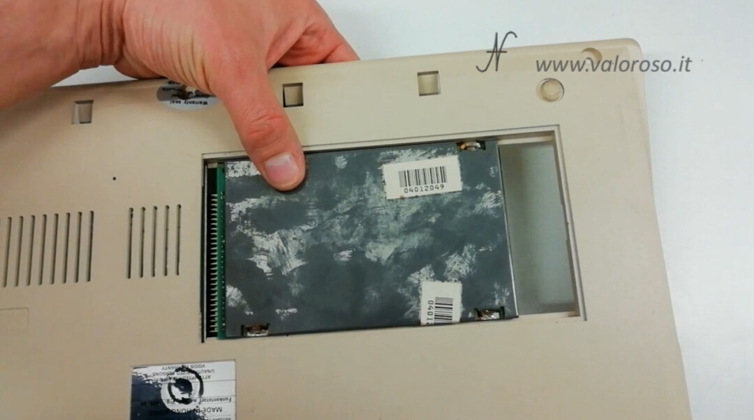
When the expansion card is free, we can slide it out of the case.
Removal of the lower metal shielding of the Amiga 500
After removing everything connected to the motherboard, it slips out of the computer case. However, it is not free: there is still a metal shield attached to the motherboard. To separate the PCB from the shield, you need to unscrew the nuts / turrets that hold the connectors to the shield.
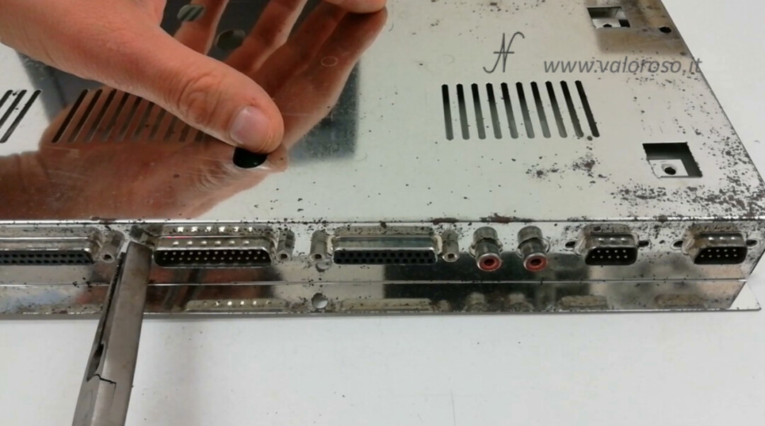
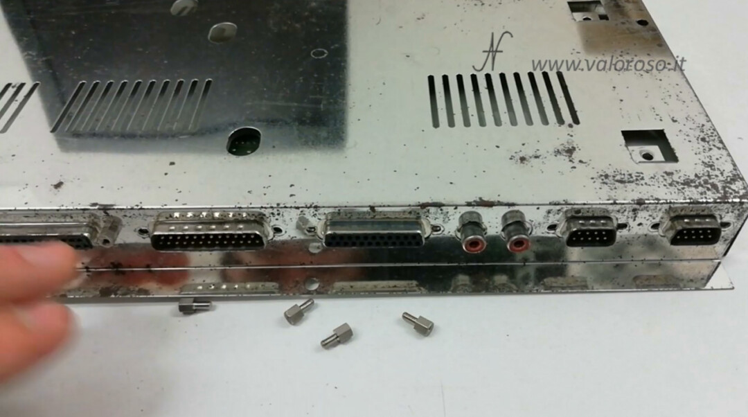
Now we can separate the motherboard from the metal shield.
To avoid losing the smaller components and small parts, I suggest storing everything in a transparent bag.
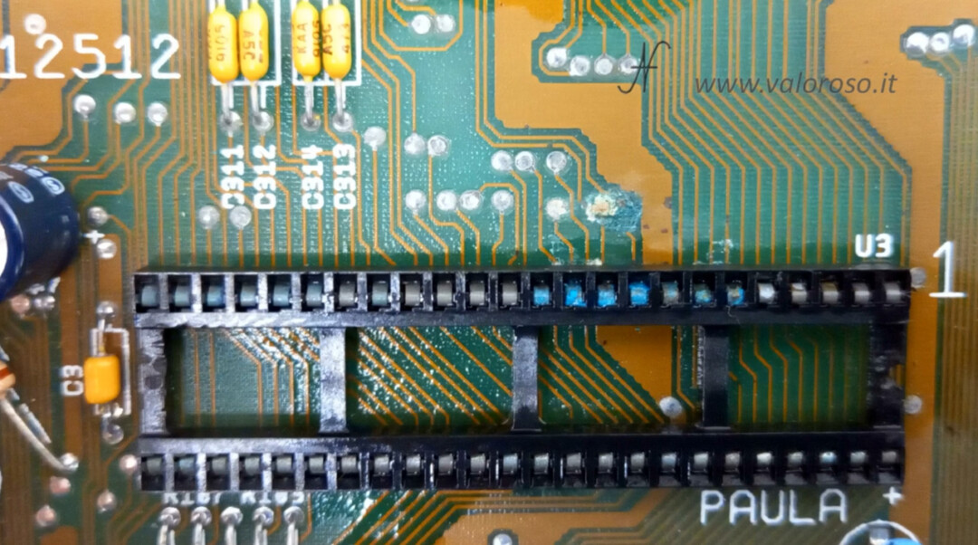
Dism the oxidized clover from the motherboard of the Amiga 500
The motherboard has corroded tracks and an oxidized socket. We will have to rebuild the tracks and replace the chip socket.
Finally I have the opportunity to use the uncomfortable station that I just bought: a ZD-8915. In the video, from 9:35, there is a tutorial on how to set up and use the uncomfortable station. The steps are listed in this article.
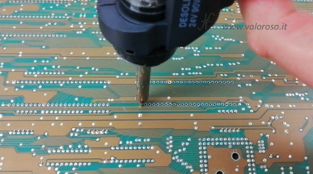
After unloading the socket from the printed circuit board, it is clear that the oxide had also insinuated below the Paula chip.
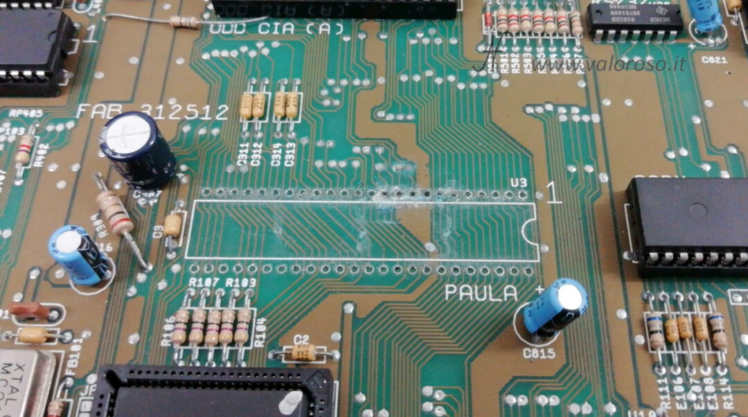
We can clean the PCB again with alcohol and flux.
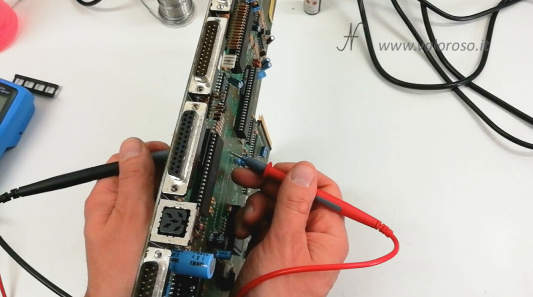
Test the PCB tracks with the tester
Now, you have to try which PCB tracks are working and which are broken. Through the tester we do several tests. The operation, honestly, is a bit boring!
The first test we must perform concerns the metallization holes in the PCB. It is necessary to check if there is electrical continuity between the upper and lower side of the printed circuit board, on the same pin as the integrated circuit.
This test must be carried out for each pin of the removed integrated circuit: on the single pin, there must be electrical continuity between the upper and lower layer of the PCB.
Then, we prove that they are not there short circuits between the pitches and adjacent tracks of the printed circuit board.
Obviously, it is necessary to find electrical continuity only between pins connected by the same track of the printed circuit board. It is normal to find a certain electrical resistance between different pads of the PCB, but it does not have to be a continuity (resistance = 0), if there is no track that connects them. If you find tracks passing between two IC pitches, you will need to prove that the tracks are not short-circuited with adjacent pitches.
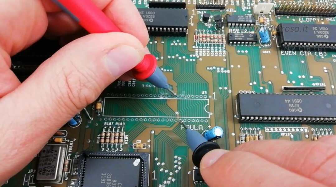
Finally, let's try the continuity of the slopes that connect the various pitches to each other.
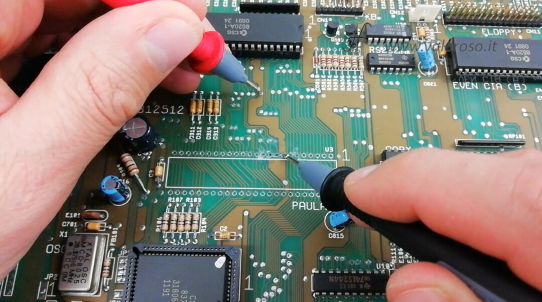
In practice, we follow the track between the pad of the chip that we have removed and another where the track ends: there must be electrical continuity. An IC pad can be connected to multiple tracks - you need to try them all.
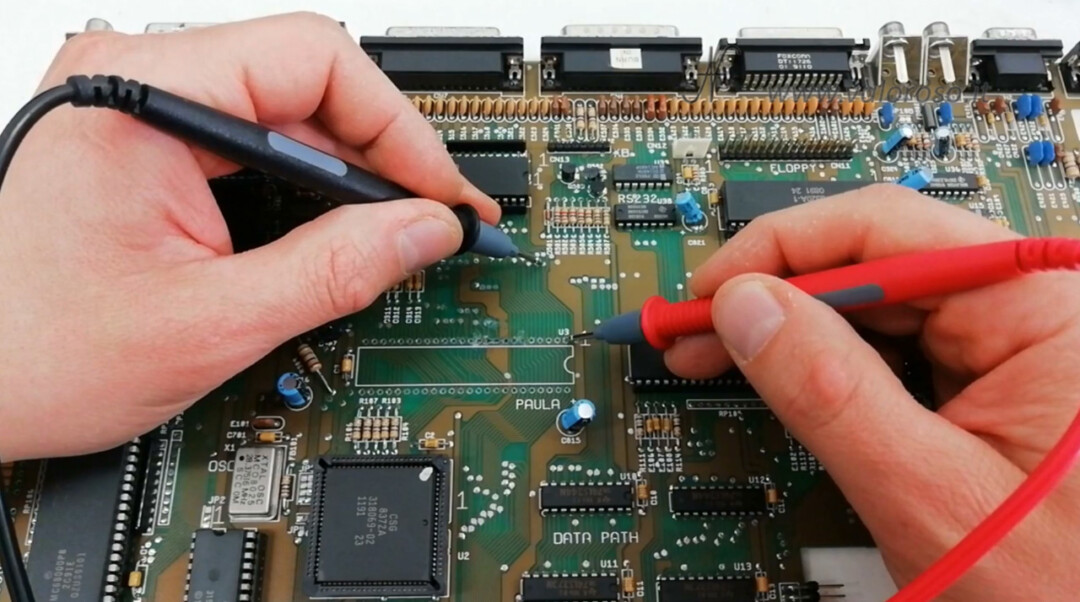
This test must be done on both layers of the printed circuit board.
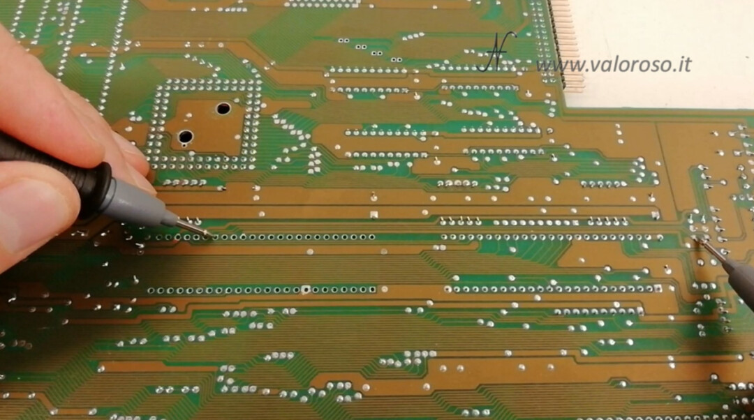
The circuit board test showed three broken tracks, all in the top layer, above the Paula chip. There were no short circuits and interrupted traces in the lower layer of the PCB.
Continues...
We will proceed with the repair of the Amiga 500, the reconstruction of the three tracks, the assembly of a new socket and the test in other video articles.
To be notified when I publish the other videos on the Amiga 500, and also the other videos related to retro computers and vintage electronics, I invite you to subscribe to the YouTube channel and activate the notification bell!
Ciao Amedeo complimenti per il video, sto restaurando un Amiga 500 che ho acquistato in parte smontata e desideravo fare una domanda, il floppy drive viene tenuto da 4 viti, 3 sono della stessa lunghezza ed una è qualche millimetro più corta, in sostanza 2 viti sulla parte sotto si avvitano su 2 riser a sua volta avvitati al floppy, un altra si avvita direttamente al drive, e l'altra tramite una rondellina tiene il floppy lateralmente, non riesco a capire quella più corta dove va, escluderei sui riser poichè è una sola, visto che lo hai smontato da poco ricordi la posizione?, grazie
Hello David! Thank you very much! In my video, I remove the floppy from minute 7:20 onwards. You can see the 3 lower screws (2 are with turrets) and then a side screw.
I have an Amiga 500 complete with Commodore 1084s monitor, LC 200 printer, mouse, 1 joystick, Workbench 1.3.2 disk + Extras 1.3.3 disk + dozens of non-original game disks, is anyone interested?
Surely someone is interested, you can try to sell it on immediately, Facebook Marketplace, etc ... I recommend the sale of person.