In this tin soldering tutorial, we build a MP3 to C64. In practice, it allows you to load and record programs, games, using the Commodore datassette port. I take advantage of the assembly of this circuit to show you how to solder the components on a printed circuit through hole.

Via the MP3 to C64 (MP32C64), Commodore programs are recorded and loaded as audio files, both on smartphones and other devices. The video is a tin soldering tutorial, on how to assemble electronic circuits, on how to solder traditional through-hole components on PCBs, avoiding making mistakes.
We will see the proof of this circuit in another video!
Tools and equipment for soldering electronic components
To mount electronic components on a PCB and solder them to solder, several tools are required.
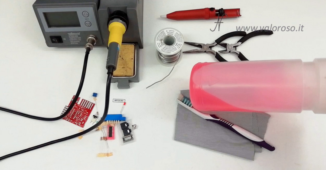
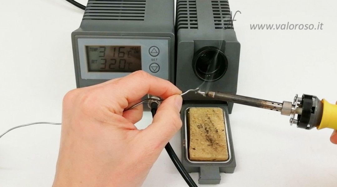
First you need the welder: I have an adjustable temperature soldering station. The station is equipped with support for the welder and of sponge to clean the tip. The sponge must always be soaked in water.
The tip of the soldering iron must always be in order. Absolutely avoid cleaning it with a file or sandpaper. Better to clean it when it is hot, using a sponge soaked in water or a light wool, if it is very encrusted.
It is also necessary tin alloy. There are several types on the market. The tin that has always been used in the past was a tin / lead alloy (Sn 60%, Pb 40%), which melted at about 190 degrees. Today lead has been banned… so there are alloys of tin with other metals, which melt at higher temperatures, even at 220 degrees. The finest alloys also contain silver (Ag), which improves electrical conductivity and makes welds more shiny. In the solder tin, there are cores that contain the riverine, which cleans metal surfaces and promotes the adhesion of liquefied tin.
A can come in handy support to hold the circuit board, called third hand. And the pump sucks tin, to redo some bad soldering.
Other essential tools are: one tweezers to gently pull the component leads and the nippers, to cut them after having welded them.

And can not miss a aspirator, to avoid poisoning us with welding fumes.
To clean the printout after assembly, the advice of thealcohol and one toothbrush, as well as one rag that does not leave hair and dust.
Tin welding tutorial, checks and antistatic preliminary operations
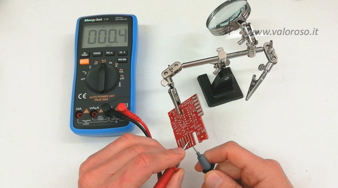
Initially, you need to check that the soldering iron tip is grounded. With the welder off and cold, you can check with the tester, testing whether there is electrical continuity between the metal tip of the welder and the earth.
Before handling the most delicate components, such as semiconductors, it is good to touch metal objects connected to earth, to discharge any build-up of static electricity present on our body.

These two operations are described in the video.
Let's take a look at the printed circuit
In this tin soldering tutorial, we assemble a kit MP3 to C64 (MP32C64) per Commodore.
The PCB present in the kit is a double-sided, with metallized holes. This means that the copper tracks run on both sides of the PCB and are connected to each other.
You can see it with the tester: there is electrical continuity between the top and bottom of a hole. In fact, the channel of the hole is coated with metal, with a process called metallization.
For this reason, care must be taken not to enlarge the holes with the drill! If the metallization is removed, the upper tracks are no longer connected to the lower ones.
If it is necessary to widen a hole (for example because the lead of the component is too thick), the component should be soldered both above and below the printed circuit, to restore electrical continuity.
All the leads of the components to be assembled and the printed pitches must be beautifully shiny. If they are oxidized, they should be cleaned before soldering.
Positioning of components on the printed circuit
Let's get to the heart of the tin soldering tutorial and see the positioning of the electronic components on the printed circuit board.
It is better to start with the lower ones, so that you can place the print while welding. As some components are assembled, it is possible to solder them (as we will see in the next paragraph) and cut off the excess leads.
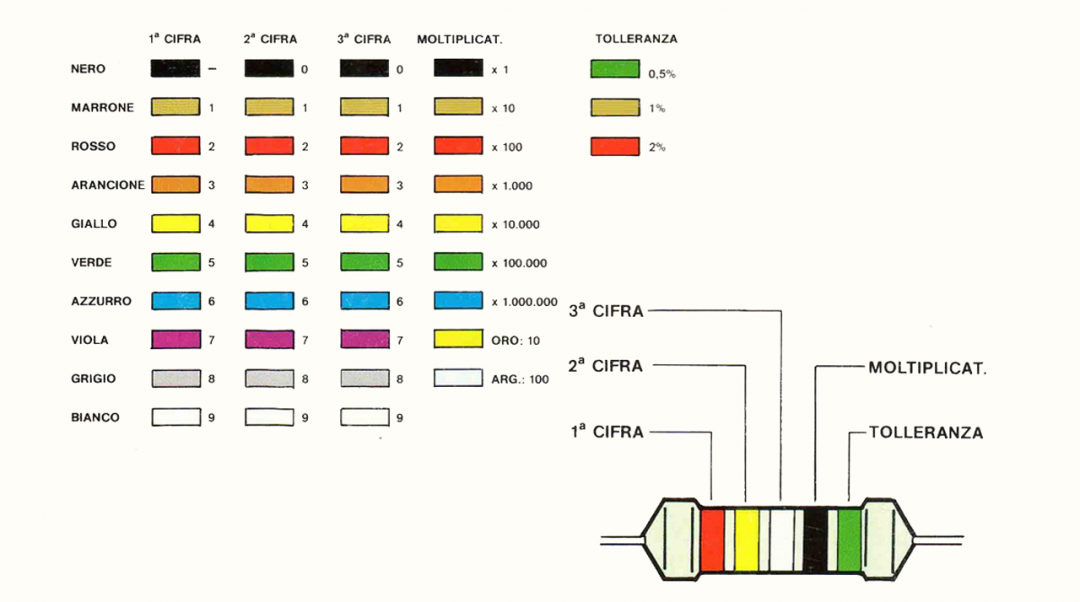
We then begin to mount the resistors (resistors). Each resistor has a different ohmic value, which is identified by the colors on the body. Normally the resistors have four color rings. The first two identify the value, the third the multiplier and the last the tolerance.
For example, this resistor has the colors red, purple and orange: the value is 27 multiplied by 1000, i.e. 27 KOhm.
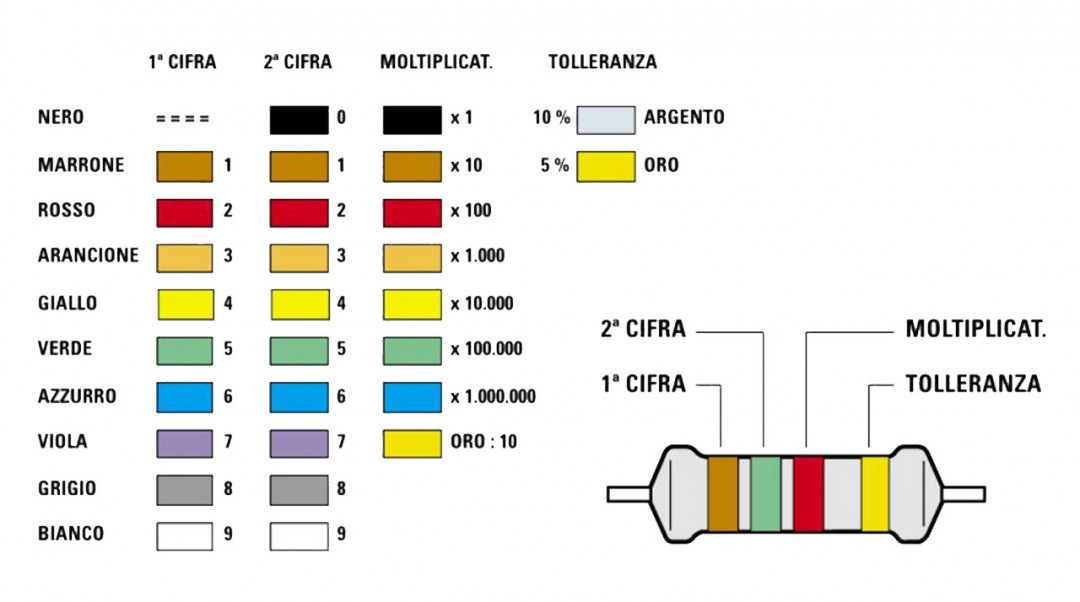
In precision resistors there is an extra color ring, therefore there are three rings that identify the value, the fourth indicates the multiplier and finally, the last one the tolerance.
The resistors have no polarity. They can be mounted in both directions, indifferently. To order, I still like to turn them all in the same direction.
As we assemble the resistors, without soldering them, we gently pull the leads with the pliers and spread them apart. This is to prevent the resistances from falling when we turn the PCB to weld them.
After having assembled and soldered all the resistors (adhering to the printed circuit), we can move on to the other components.
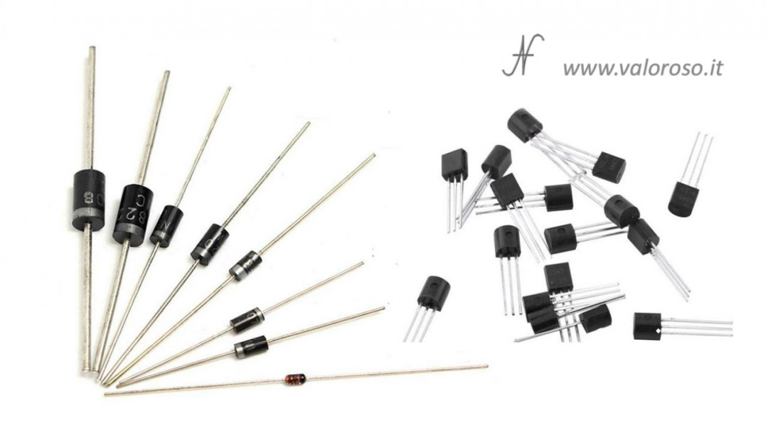
Other low components can be i silicon diodes. They must be mounted in the correct direction, identified by a band on the body. To solder semiconductors, as we will see in the next paragraph, I recommend lowering the temperature of the soldering iron.
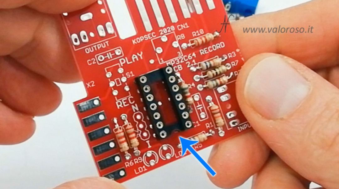
It chip socket it has a notch that is used to orient the chip in the correct position.
To hold the plinth in place, after inserting it, we can spread a couple of feet at opposite corners.
While we weld the two feet, you can press the socket, so as to mount it adherent to the printed.
After checking that the socket is adherent to the printed circuit, we can proceed to solder the other pins.
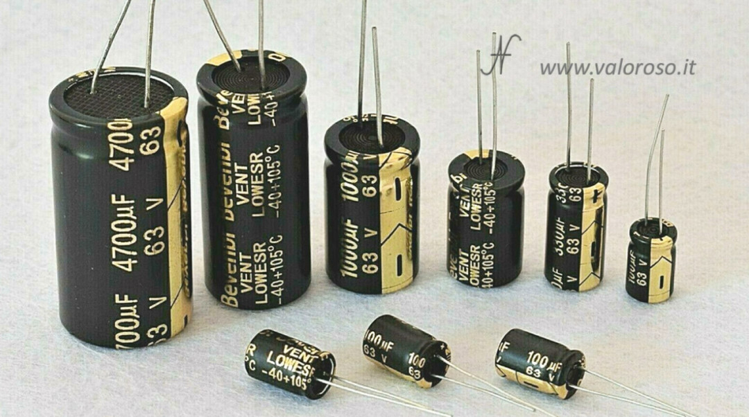
If you need to solder electrolytic capacitors or transistors, remember that they are polarized components and must be mounted respecting the correct polarity. For transistors, it is recommended to lower the temperature of the soldering iron.
Now mount the two jack plug connectors, the trimmer and the non-polarized capacitors, always paying attention to solder them adherent to the printed circuit.
I led they are polarized and moreover delicate components. They must be inserted in the correct direction and welded quickly. For safety, you can also lower the temperature of the soldering iron.
We try to mount them straight by first soldering one lead, then straightening the led, and finally soldering the second lead.
In the kit there are also some switches: in the video I show how to weld them.
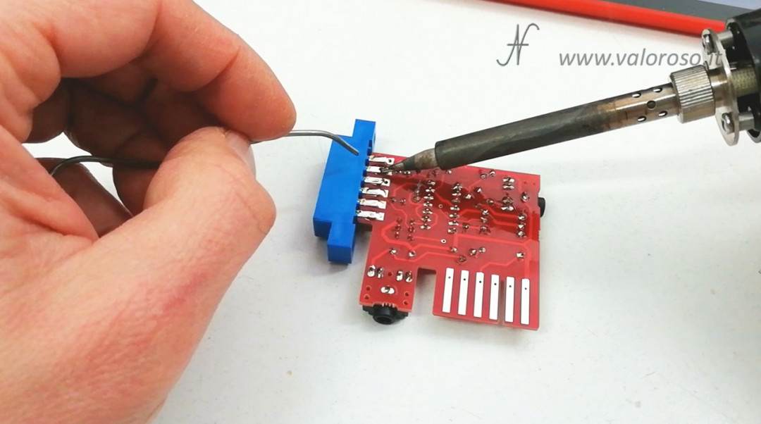
Finally, to solder the edge connector, 12 poles, of the datassette you can raise the temperature of the soldering iron: the tracks of the printed circuit board and the contacts of the connector are bigger.
I balance it, initially aligning it with the lower layer of the PCB.
Then, I bend the top tabs of the connector and secure them to the top layer of the circuit board.
Before mounting the integrated circuit in its socket, the PCB is cleaned, which we see in the following paragraphs.
Tin soldering tutorial, detailed procedure for soldering electronic components
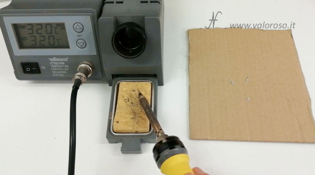
First we adjust the temperature of the soldering iron. We can start at 320 ° C, which should be a good compromise for small components. The most delicate components (semiconductors or particularly small components) can be soldered at lower temperatures, even falling below 300 ° C.
Particularly large components or with very large pitches on the printed circuit must be soldered at higher temperatures, even over 340 ° C.
Temperature measurement is not always accurate on soldering irons, so you may need to choose different temperatures.
To make a proper weld:
- with a hot soldering iron initially we clean the tip the welder with the wet sponge;
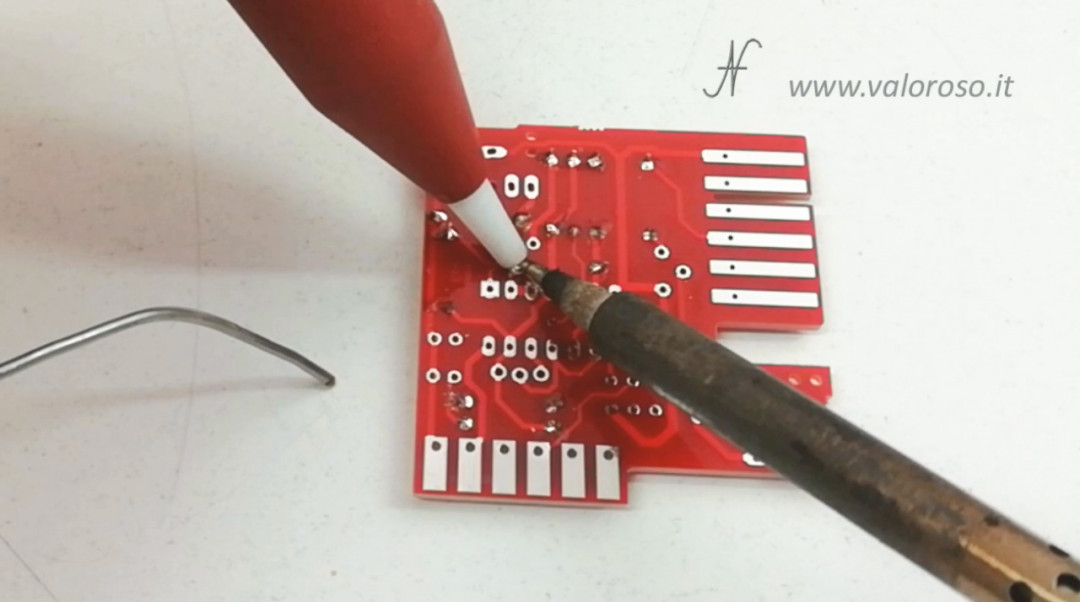
- we gently place the tip on the pad to be soldered on the printed circuit, so that it touches both the pad and the lead of the component;
- after a couple of seconds, we approach the pond, so that it melts;
- let's remove the tin and leave the soldering iron for another couple of seconds;
- finally, we also remove the tip of the welder.
The procedure is repeated for all the other leads.
When soldering, make sure that the components (which must not dissipate heat) remain adherent to the printed circuit board.
For soldering, always use fresh tin from the roll, which contains flux, and the soldering iron tip needs to be cleaned often. From time to time, we remove the old tin on the tip and then pass it into the sponge soaked in water.
The welding of the single points must take place in the times I indicated above. If you hold the soldering iron on one spot for too long, the component may overheat and be damaged. Furthermore, if the temperature is too high, or if the soldering iron is held for too long on one point, the pads of the printout may come off.
Relating to the amount of tin, must be sufficient to cover the entire pitch.
In double-sided circuits, it is good that the tin flows into the photo, even reaching the other side of the printed circuit.
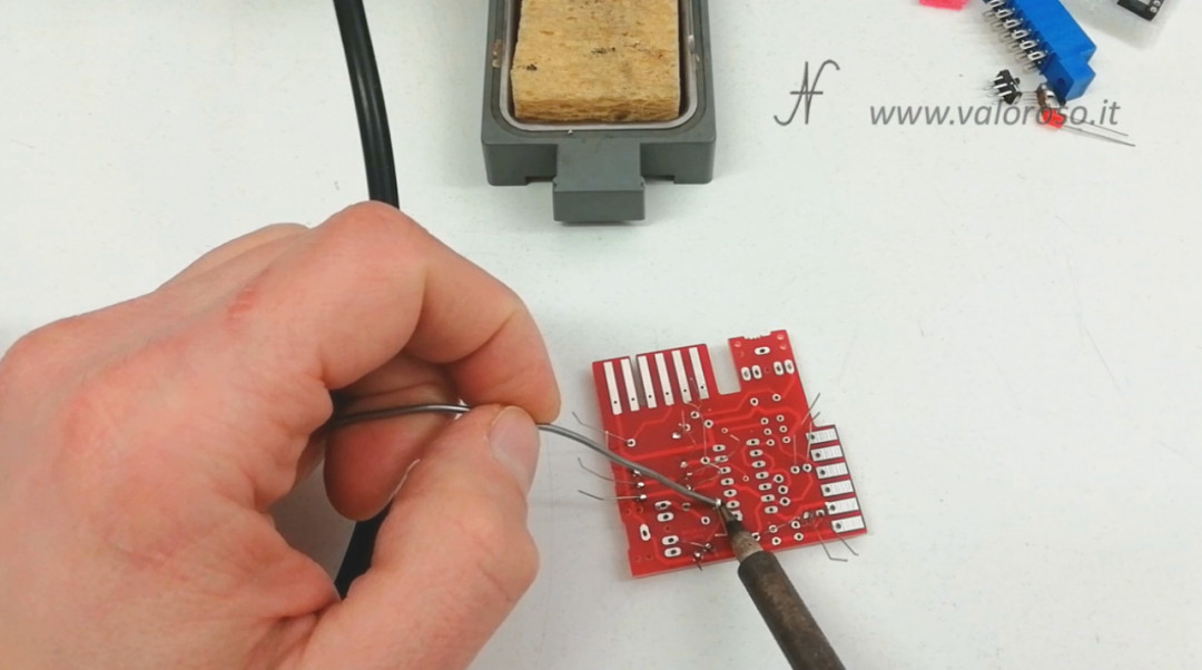
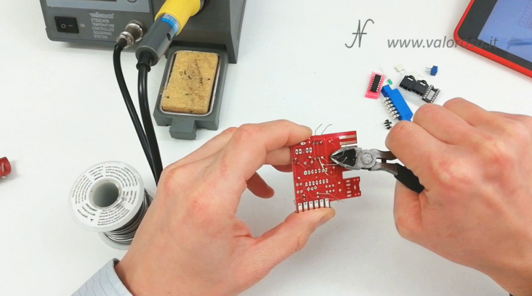
Once the components (or part of them) have been welded, it is possible we can cut the remaining lead with a wire cutter.
The welds must be as shiny as possible. Sometimes it happens that a whitish ball comes. In this case, the flux present in the pond has not done its job well, so it is good to suck up the bad solder and redo it.
Excess tin can be removed with the tin sucking pump. Then, we do the soldering again, with the new tin from the roll.
After having tinned the components, the soldering iron must be placed inside its support.
When we no longer need the welder. Before turning it off, a small amount of tin must be dissolved on the tip of the soldering iron, which is used to preserve it when we are not using it.
Cleaning the PCB after soldering
With the cooled printed circuit, you can usealcohol and it brush to remove the flux residue that was in the pond. We use it tore up to clean both the toothbrush and the printout itself.
We repeat the operation several times, until the printout is glossy and no longer sticky.
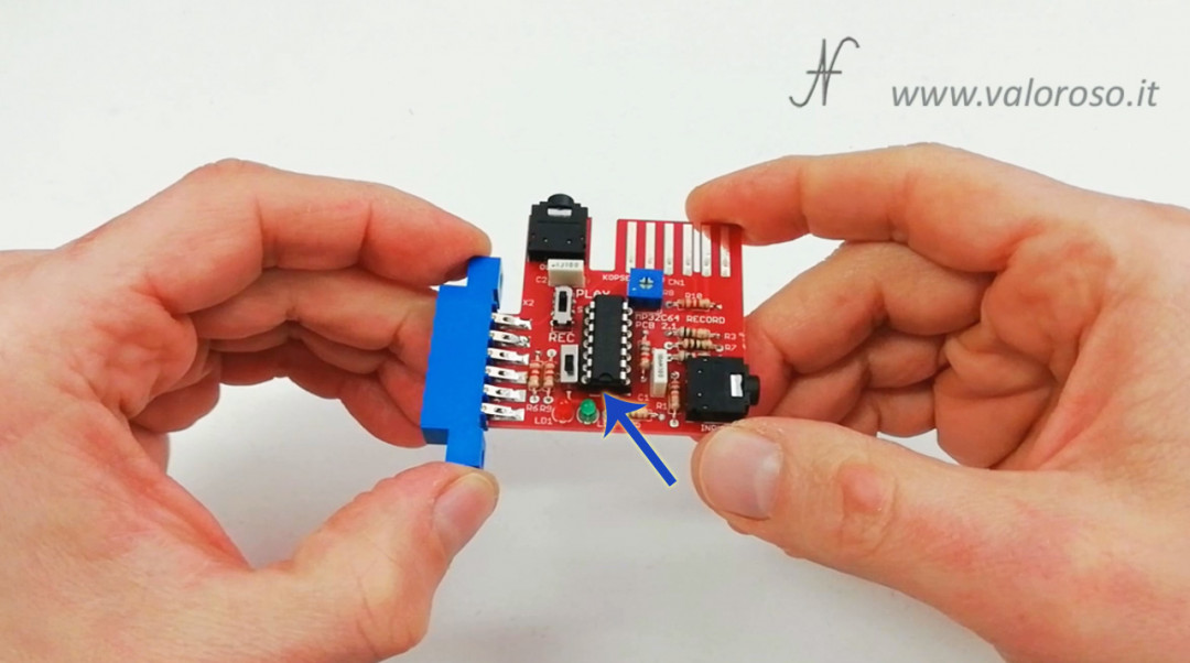
After cleaning, we can insert the IC into the socket.
Tin soldering tutorial, insert the ICs into the sockets
To insert the chips into the sockets, you need to slightly bend the feet, side by side, pressing the integrated on the table top.
When the pins have reached the correct width, we can insert the integrated circuit inside its socket, respecting the polarity. In fact, the integrated circuit has a notch, which must be aligned with that of the socket.
Final checks
I end this tin soldering tutorial with a tip: before testing the circuit, take a few minutes to check that you have mounted the components with the right values in the correct position!
Credits: in the video tutorial, the music is “Super Cars II (1991) intro theme by Ian Howe”.
Hi amedeo,
Excellent video, very well commented.
I would like to add a link to your video in my eBay add, I’m the seller of the MP32C64 (cespok_64) and you video is really well done and it can help many users to assemble the device. Nice video also loading from open reel !!!! We tried to load to a C64 from a 33rpm vinyl but only managed to load the title!!!!!
Cheers
Big
Hello Mari! Thank you for your comment. Of course you can share my video. Load from a vinyl? Nice experiment!
Amedeo, congratulations for the realization of your videos always impeccable, also full of Humors.
I want to ask you but the MP32C64 card, it is also already beautiful that ready??
Can you give me the address of the seller ??
Thank you so much for what you do, keep it up. ;-))
Thank you very much! The MP32C64 card is also found already mounted. The kit that I bought (and that is also already assembled), I took it on eBay from cespok_64. Check the model of MP32C64 purchases well, because there is the one in read only and the one in read and write.
Amedeo, good afternoon, excellent video, I expect to see soon more tutorials on this topic welding and on this MP32C64 card. Greetings.
Thank you!