I recently bought a WiFi modem on eBay and I had written an article on how to configure and use it. And now, why this article? Is a modification to the WiFi modem for Commodore 64 really necessary? It has been pointed out to me that these modems, very often, are not well designed and now I will explain why.

The modem module, in fact, works at 3.3V, and is not completely 5V tolerant, as many would have you believe! The Commodore 64, on the other hand, powers 5V. It is true that, on the modem, there is a voltage regulator that lowers the supply voltage from 5V to 3.3V. Despite this, there remains a modem data pin into which the 5V voltage of the Commodore 64 is directly injected. This leg, however, withstands only 3.3V! This design error can create problems, both for the modem and for the Commodore!
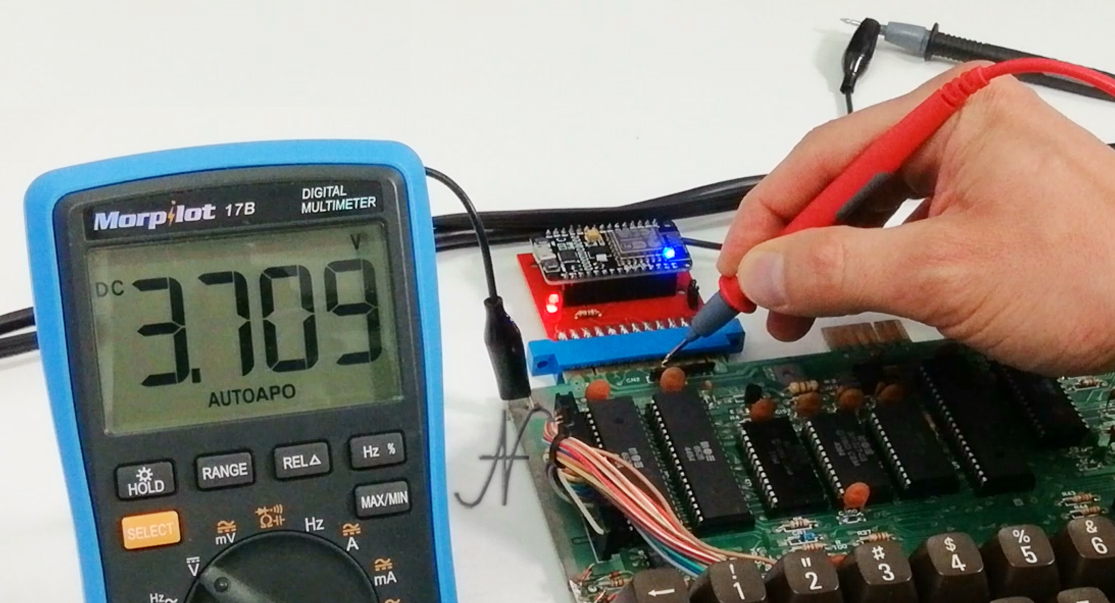
The result of directly connecting the 5V signal output of the Commodore 64 to the RX entrance of the WiFi modem module (the ESP826MOD) is a completely incorrect voltage, of 3.7v.
A pole of theory
Here is the original schematic, incorrect, of the WiFi Modem for Commodore 64. You can see all the direct connections, between the Commodore user port to the NodeMCU module, which mounts the ESP8266 chip.
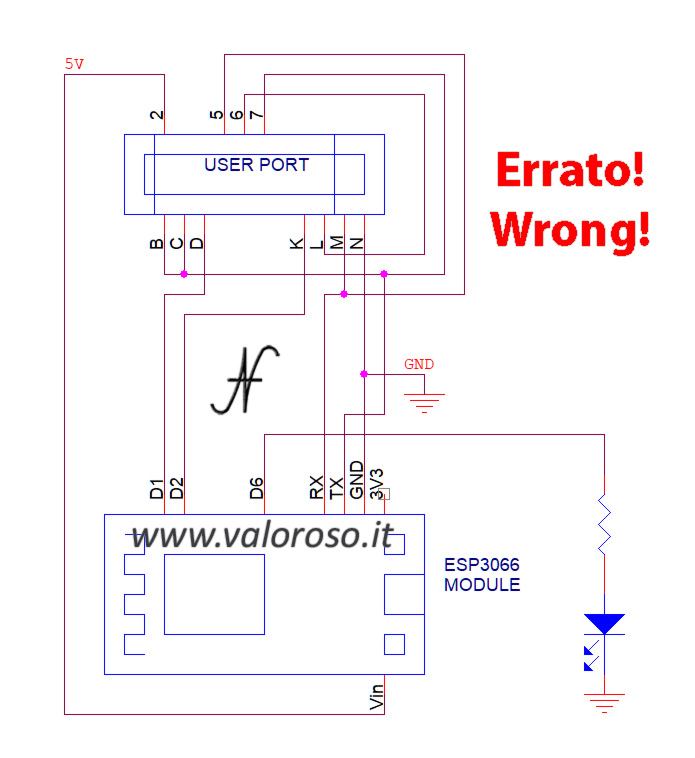
I measured the tension on all the pins and the only one that is in suffering is the RX of the module, which is connected to the M and 5 pins of the user port of the Commodore 64.

Changing the WiFi modem for Commodore 64 is very simple to do. Indeed, just add a diode. I noticed that, inside the WiFi modem form, there is already a pull-up resistor, which requires 3.3v when no signal is placed in the RX pin. The Commodore 64 also has a pull-up resistor on pin 5 of User Port. It can be seen by consulting the service manual on page 13 of the manual (it is 17 of the PDF file).
What is needed to reduce the 5v of the Commodore exit, bringing the voltage to 3.3v is called Level translator. Many use a simple resistor to perform voltage reduction. At least in this case, it is not a good solution, precisely because there are pull-up resistors in both the WiFi module and the Commodore.
The simplest solution to make a level shifter, in this case, is to insert a diode, type 1N4148, between the RX pin of the WiFi module and pins M and 5 of the Commodore user port. Even if the 1N4148 diode fits perfectly within the required voltage and frequency tolerances, whoever wanted to could use a Schottky diode, which has better performance. For practical purposes, however, no difference would be found.
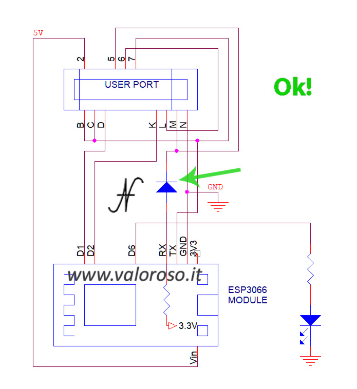
The diode, facing the cathode towards pins M and 5 of the user port, is used to pass only the logic level 0 (voltage tending to 0V) from the Commodore to the modem. Instead, the logic level 1 (voltage tending to the supply voltage), is provided by the two pull-up resistors (those already present in the modem and in the Commodore).

Modem to the WiFi Modem for Commodore 64: the hardware part
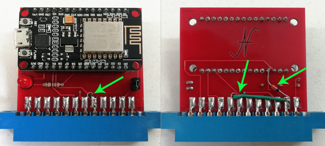
The modification to the WiFi modem for Commodore 64 is not only theoretical but also practical. It is necessary to cut the track that carries the signal to the RX pin of the WiFi module, leaving pins M and 5 of the Commodore user port joined together. Then you need to solder the diode between the RX pin of the WiFi module and pins M and 5 of the user port. The diode is a polarized component: the band that identifies the cathode must face towards pins M and 5 of the user port. Here is the result I got in the picture.
After the modification, I analyzed the voltages with an oscilloscope. It can be seen that, after the modification to the WiFi Modem for Commodore 64, the maximum voltage on pins M and 5 of the user port is no longer 3.7V, but about 5V, as it should be. Furthermore, the maximum voltage on the RX pin of the ESP8266 WiFi module is no longer incorrect at 3.7V, but corrected at 3.3V.
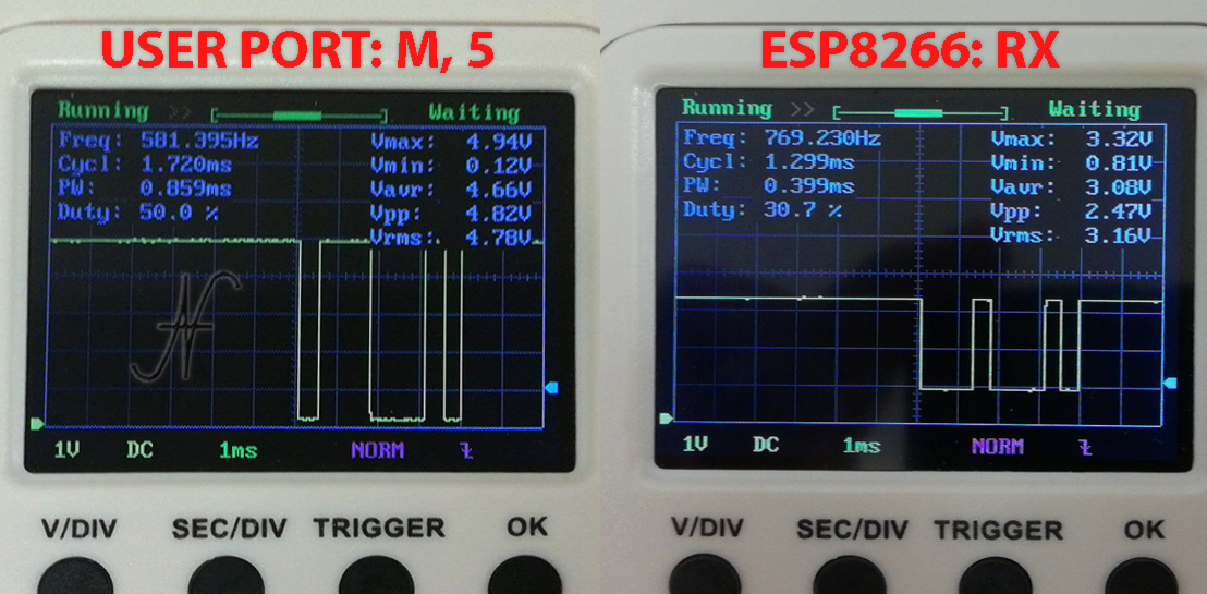
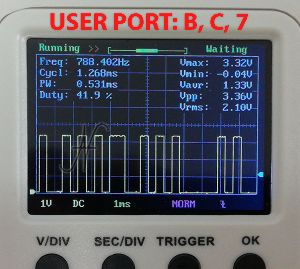
No changes have been made to the other pins, which however have no problems. For example the TX pin has a maximum voltage of about 3.3V, which is correct for the ESP8266 WiFi module. The voltage is also within the tolerances of the Commodore 64 user port inputs.
Is it necessary to change the WiFi modem for Commodore 64?
Change or not change the modem? Online, there are conflicting opinions.
"Non ho mai visto rompersi alcun Commodore 64 per aver installato questi modem WiFi!"
"Le correnti in gioco sono molto piccole e non possono creare danni!"
Of course, everyone has their own opinions. Now, however, we know that:
- the components work with wrong voltages;
- the modification to the WiFi modem for the Commodore 64 costs very little.
Inoltre, per completezza, allego il documento "hardware design guidelines", del produttore del modulo ESP8266: Shanghai Espressif Systems. A pagina 11 del documento, che corrisponde alla pagina 15 del PDF, si evince quanto segue: "The IO of the ESP8266EX is a 3.3 V logic level. In the case of serial communication with a 5 V CMOS logic system, a level switch circuit needs to be added externally. See Figure 1-10c".
The change, in my opinion, must be done!
Excellent intervention that I immediately performed on my homemade modem. Having no technical skills, but excellent dexterity and patience, I made one at home with a millefori and the ESP8266MOD module.
Very interesting what you do, I continue to follow you on Youtube.
Regards.
Hello! Thanks so much! You did well to build the modem on millefori. In case of upgrades or modifications, you already have space to mount the new components.
This is a very insightful explanation of the voltage compatibility issue between the Commodore 64 and the ESP8266 modem module. It highlights how small hardware design oversights can lead to reliability and safety concerns in retro-computing projects. Understanding signal levels and proper voltage conversion remains essential for electronics enthusiasts and students alike, especially in fields related to embedded systems and IoT.
Thank you!