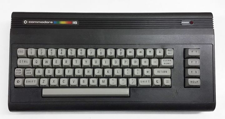
Here's another retrocomputer article: the repair of a Commodore 16. Sifting through Facebook Marketplace, I was struck by this insertion relating to a used, not working commodore 16. The price was good, precisely because the computer had problems. According to the seller, the power supply was damaged: he could not repair him, so he sold the Commodore 16, with his accessories, at a low price.


I therefore decided to buy the lot composed of: Commodore 16 with a power supply to be repaired, original joystick, boxes with games and reader of boxes given 1531. When I received the Commodore, I immediately started working. The computer presented itself very well, even if it was definitely dirty. The power supply was disassembled: it was sufficient to reassemble it to make it work. Unfortunately, however, the Commodore 16 was not working!
Brief history of the C16
The Commodore 16 was marketed by the CBM (Commodore Business Machines Inc.) in 1984. It was the economic alternative of the Commodore 64, which I will speak in another article and on which I did several experiments.
You can actually notice the economy of the computer from some circuit solutions adopted:
- the absence of a sid chip (audio chip);
- a lower amount of RAM compared to the C64 (16kb RAM total, of which 12277 free to ignition);
- a linear power supply of inadequate power, with resistor R10 to help and lack of filter capacitors.
The C16 used a CPU signed MOS 7501 which, subsequently, was updated with the most recent MOS 8501 (the one present in the computer I repaired). Unfortunately, the Commodore 16 did not meet the public's favor, so much so that production ceased the same year.

Commodore 16 Repair
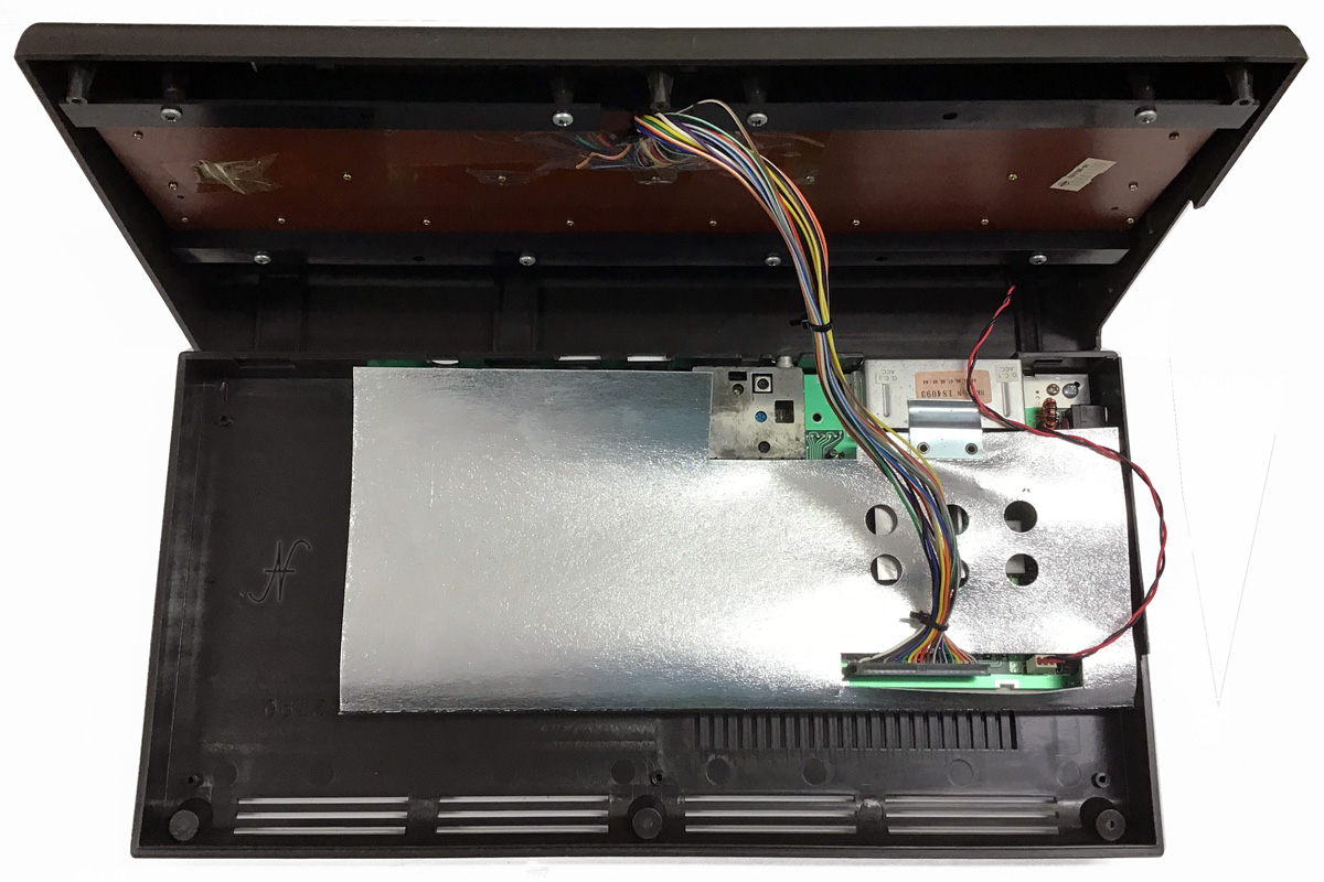
Returning to the repair, I opened the Commodore chassis and I disassembled all the internal components. I realized that the fuse on the motherboard was interrupted. Not having fuses of that size (6,3x32), I used a 5x20 fuse, of the same amperage as the original one. I also inserted a filter capacitor, since I realized that the power supply on the motherboard was without it.
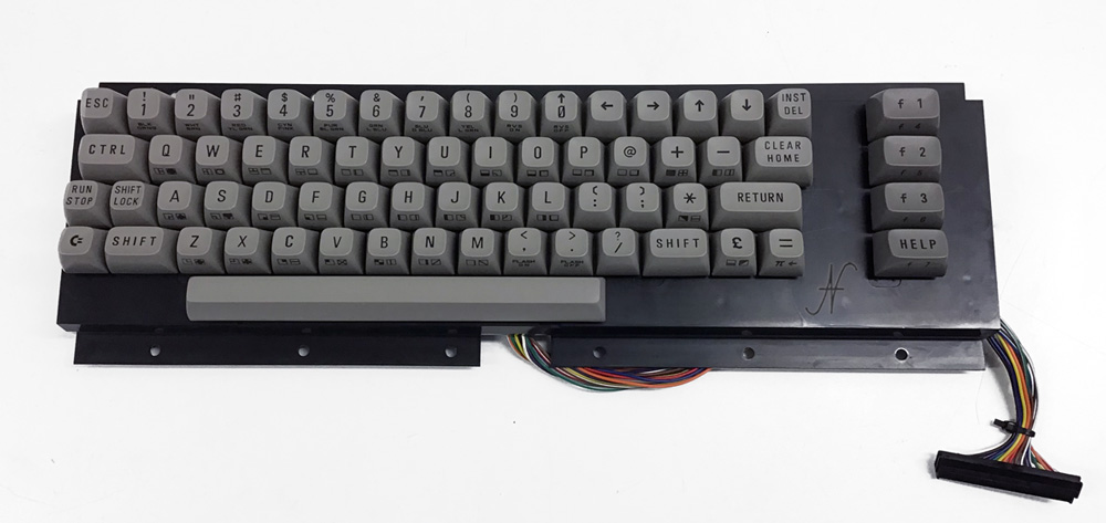
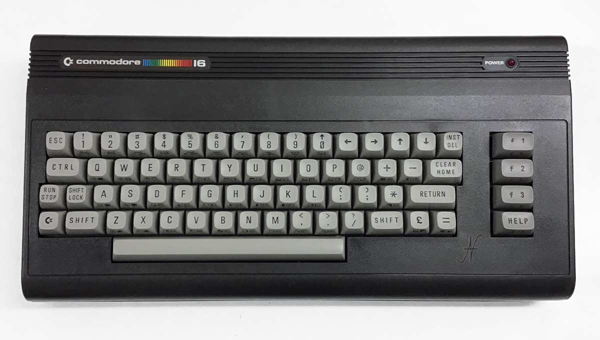
With these simple interventions, the Commodore 16 repair was successful and the computer immediately started working. I then dedicated myself to the complete cleaning of the chassis and keyboard.
Commodore 16 recapping
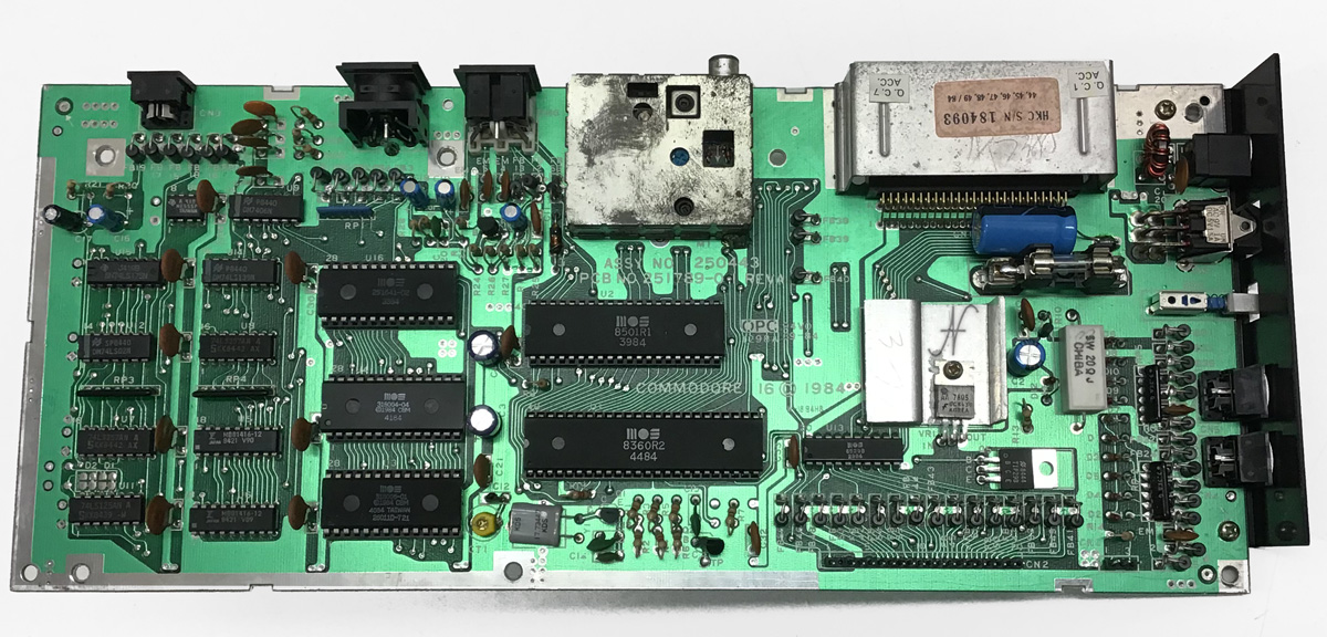
I performed a complete rescapping of the Commodore 16. I replaced all electrolytic capacitors: both those of the power supply and those of the motherboard. In fact, electrolytic capacitors tend to degrade with the passage of time: losses increase, the ability tends to go out tolerance and some capacitors also go in short circuit.
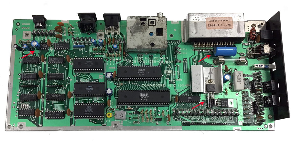
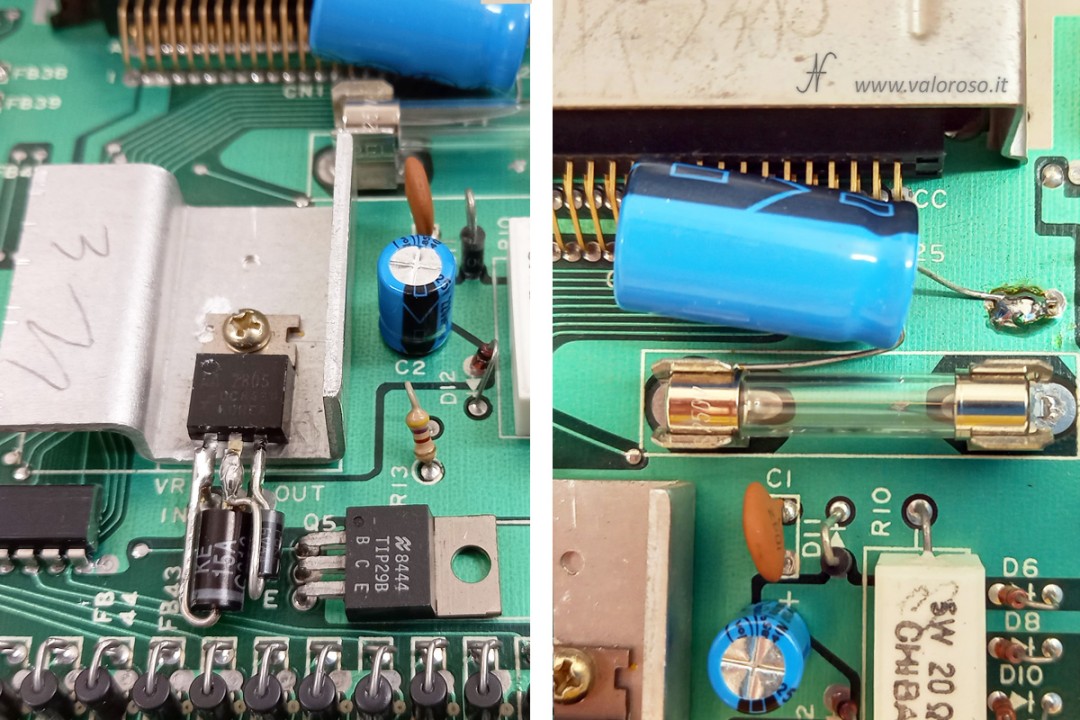
In addition to the replacement of the capacitors already on the motherboard, I also added a pair of capacitors who were, in my opinion, missing. The first (at the top right in the photo) I mounted it at the entrance of the UA7805 linear voltage regulator, in order to make up for any voltage changes. He is a 1000uf capacitor, minimum 25v, in my case 50v. I inserted the second capacitor when the regulator exits, on the 5V line (you can see at the top left in the photo). The value of the second capacitor is 220uf, minimum 16v: I used a 25v one.

Regarding the original capacitors, I made some changes (optional):
- C2, initially from 47uF, is now from 220uF, minimum 16V;
- C3, initially from 10uF, now it is from 100uF, minimum 16V;
- C4, initially from 10uF, is now from 100uF, minimum 16V.
This change is used to increase computer immunity to any sudden voltage drops.
Warning! The capacitors are polarized, which means that the positive pole must not be inverted with the negative!
Protection of the Commodore 16 from voltage transients
Finally I protected the motherboard and the external power supply with some Transyl (on the continuous current 9V and 5v lines) and with a varistor on the primary of the 230Vca transformer. The Transil before the regulator is a 1.5ke15a. The one after the regulator, on the 5V line, is a p6ke6v8a. Also in this case, you must pay attention! Transils are polarized, therefore they must be welded with the correct orientation! The varistor on the primary of the 230V transformer is an S10k250 Siov.
The transils and the varistor are tasked with protecting the Commodore 16 from surges and voltage transients.
After all these repairs and renovations, the Commodore 16 is ready to run for another 40 years!
Documentation
In support of this article, I also attach the Commodore 16 Service Manual. It is a useful technical manual to understand the functioning of the Commodore 16 circuits and can be convenient to carry out repairs.
Hi Amedeo
Congratulations on this guide and thank you for the passion you put into it.
I am in the process of restoring a used commodore 16 I wanted to ask you about the (add-ons) you used in yours described in this guide and the values. Thanks in advance
Hi Sebastiano and thanks for the comment!
Taking advantage of your report, I have modified the article, including the components also in the text.
Here is the list of additional components.
Varistor on the primary of the 230V transformer:
SIOV S10K250
Transil ropo the regulator (on the 5V line):
P6KE6V8A
Transil before regulator:
1.5KE15A
Capacitor on the 5V line:
220uF minimum 16V, in my case 25V
Condenser before regulator:
1000uF minimum 25V, in my case 50V
See you soon!
Hi Amedeo,
Sono riuscito a trovare una persona che mi farà il Recap del C16 ma dovrei spiegargli nel dettaglio dove piazzare i componenti aggiuntivi che hai usato per la tua "mod", i due condensatori e i transil. I condensatore da 220uF è piazzato in corrispondenza di 2 pad vuoti li nella zona ma sono collegati proprio li passanti o come, il positivo nel pad superiore lato connettori?
The 1000uF capacitor instead seems radial to me (not axial as for the C64) but apart from that the positive is connected on those 3 pads on the right all together and the negative where?
For transils instead cut the line IN to the left before the regulator and make a bridge with 1.5KE15A (positive card side, negative regulator side) and then cut the OUT line to the right of the regulator and make a bridge with P6KE6V8A (positive regulator side, negative card side), I do not understand from the photo if the line in the center of the regulator remains intact?
For the transformer instead I use a non-original 9V stabilized with inverted poles, can I continue to use it or does the mod provide that you must necessarily use the modification also on the original transformer?
In case you can take more detailed photos? thank you very much and congratulations also for the youtube channel!
Hi Nicola. Thanks for the compliments. The change is not invasive: there are no slopes to be cut nor holes to practice. The 220uf capacitors are placed in correspondence with the empty pads, taking advantage of the existing holes (which open by sucking the solder, if they were closed). The 1000 UF is radial, because I already had it so. You can also use an axial if you prefer. The negative is in Massa, while the positive is at the entrance of the voltage regulator 7805. For the Transil, they are in parallel with the power lines, without cutting anything. They are connected to the pins of the regulator, in parallel. Pay attention to the white bands on Transil, since they are polarized. Attention! If your technician is expert, he knows how to install changes! The article is a bit technical, but, if one knows what he is doing, the instructions are clear. Don't take an improvised technician, otherwise run the risk of making damage! The stabilized transformer, as you say, is fine. The changes, which I suggest in this article, are used to protect the C16 more and are good for both original and competition feeders. PS: I don't think I have more detailed photos. Generally, I already publish those that came better.
Thanks Amedeo for updating the images, now you understand well where and how to intervene, I correct my previous comment saying then that the 1000uF capacitor has the NEGATIVE connected on those 3 pads on the right and the positive in practice welded on the output fuse holder as clearly now you see from the new images.
I would add for completeness that the additional 220uF capacitor at the top left next to the 555 must be inserted with the positive at the top, exactly like the C2 that you see well in the photo.
Speaking of C2, the diagrams and on my C16 this capacitor is 47uF while from the photos of your recap I seem to see that it is 220uF, am I wrong? is it okay anyway?
Hello Nicola. To study the recap and positioning of transils, I started from the schemes in the service manual, which you can find here: https://www.valoroso.it/wp-content/uploads/Commodore-16-service-manual.pdf
You can see that the C2 condenser is placed just after the voltage regulator exit. 47UF is a little little, considering the absorptions involved. For this, I have increased the value to 220uf. The same goes for C3 and C4, now from 100uf. These changes are optional, the original values can also be preserved.
Good evening Amedeo,
I'm subscribed to the channel and I always follow you willingly, I have a C16 with a black screen.
I am not an electronic expert and I don't have an oscilloscope, I would like to know how I can test (without a forklift) Ted, Pla, CPU ... but I have a tester 🙂
Thank you and congratulations for your videos and clarity!
Leonardo
Good evening. Thank you very much! In reality, one tester may not be enough. With the tester he can see if the supply voltage reaches the various chips. Starting with the wiring diagrams, which you can find at the bottom of the C16 page of my collection (https://www.valoroso.it/commodore-16-computer/) you have to follow the signals and clocks. An oscilloscope or frequency meter can help. However, having a working computer to swap chips helps save hours and hours of work!