Here, finally, is the test of the Commodore PET CBM 8032 that I had bought on eBay in the United States and which I had told you about in this video. I found a way to power it at 110V!

I hope you can get some ideas if you need to power some of your computers that run at 110V.
Power a computer at 110V
Computers arriving from the United States run at 110 Volts 60 Hertz. In particular, the Commodore PET CBM 8032, which I bought on eBay in the States, runs at 117V 60Hz, consuming just over 100W.
I found this transformer on Amazon: the Bronson++ VT-300. It transforms 220V to 110V, but does not change its frequency, which remains at 50Hz.
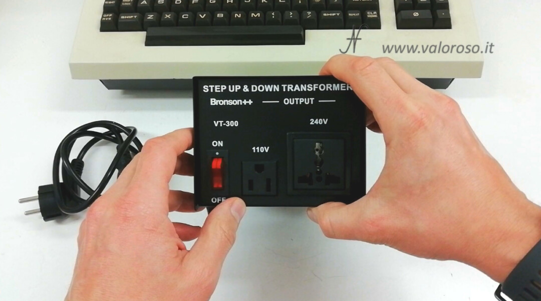
The Bronson++ VT-300 transformer has a power of 300 Watts (200W continuous), so it is suitable for the power drawn by the Commodore PET CBM 8032, which consumes just over 100W.

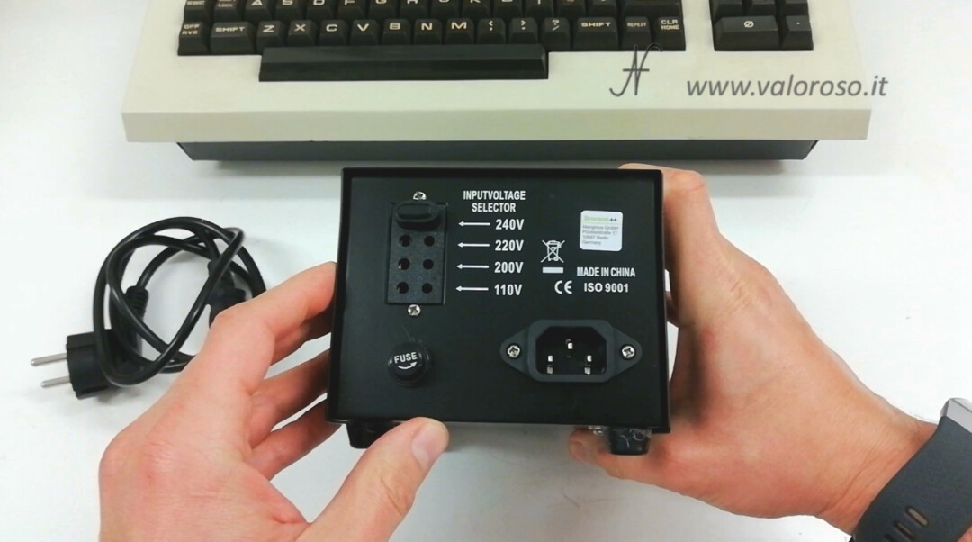
Posteriorly, has the entry of power. The supply input voltage can be set via a selector: 110V, 200V, 220V, 240V RMS.
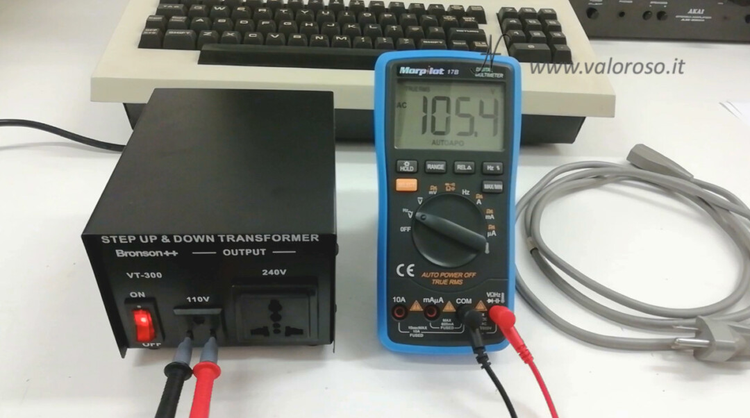
In front, the Bronson ++ VT-300, has two releases: one at 240 V with English plug, one at 110 V with American plug. By selecting the power entrance to 240V, the front exit is at about 105V.
What happens if I power a 110V 60Hz to 50Hz transformer?
Before doing the test of the Commodore PET, CBM8032, to be more aware, we study some transformers theory!
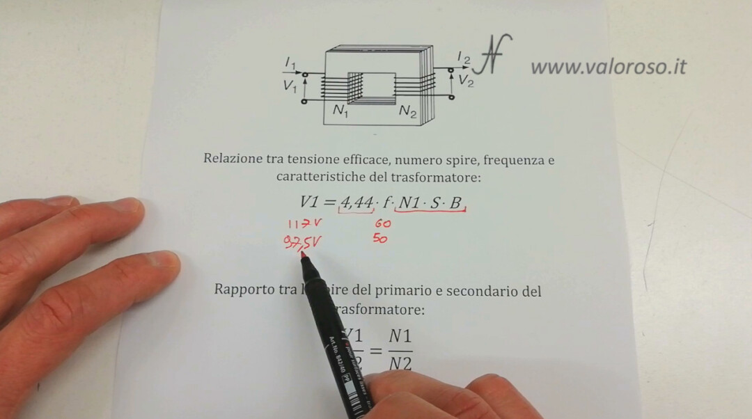
A transformer is formed by a primary winding, the one we connect to 220 Volt or, in the case of my PET, to 110 Volt 60 Hertz, and one or more secondary windings.

The windings are magnetically connected to each other via the air gap. The first equation we see is related to the nominal voltage of the primary winding (V1).
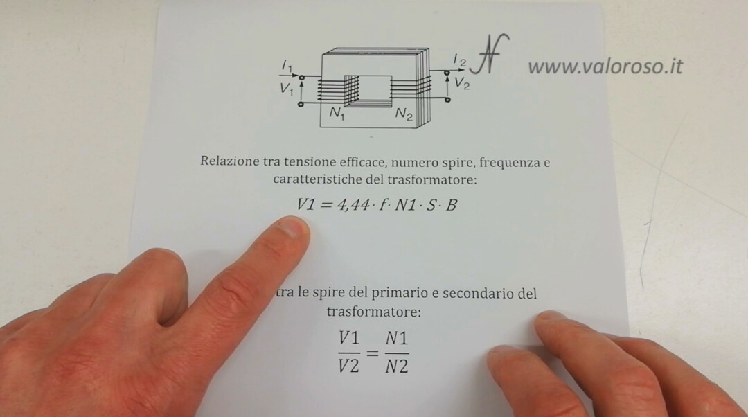
V1 = 4,44 * f * N1 * S * B
The nominal tension of the primary winding (V1) depends on the frequency f, by the number of turns N1 of the primary winding and from other factors that we see shortly.
In this case, the nominal tension of the primary elected (V1) is 117 Volt, we read it from the rear plate of the Commodore PET CBM 8032. The three factors (N1 * S * B) are constant, because we do not modify the transformer:
- N1 It is the number of spire of the primary winding;
- S and B represent the shape and material of the metal.
4.44 is a number, that is, a constant by definition.
So, if V1 It is equal to 117 effective volts at 60 Hertz, we see that, lowering the power frequency to 50 Hertz, the tension of the primary elected elected is also lowered, which therefore passes to 97.5 volts as an alternation, RMS.
Here, it is as if we no longer find a 117 Volt transformer, but, rather, a transformer of just under 100 Volts, which we have to power with just over 100 Volts. Somehow, we are a bit comfortable that the Bronson++ VT-300, which I bought on Amazon, gives me an output voltage of 105 Volts, instead of 110V.
Questo, perché si avvicina un po’ a quella che è la tensione nominale del "nuovo" trasformatore del Commodore PET che siamo andati a creare immaginariamente, portando da 60 Hertz a 50 Hertz e la tensione di alimentazione.
We can also make another reasoning: what would it take to bring this transformer back to 110 volts nominal? Let's reverse the formula.
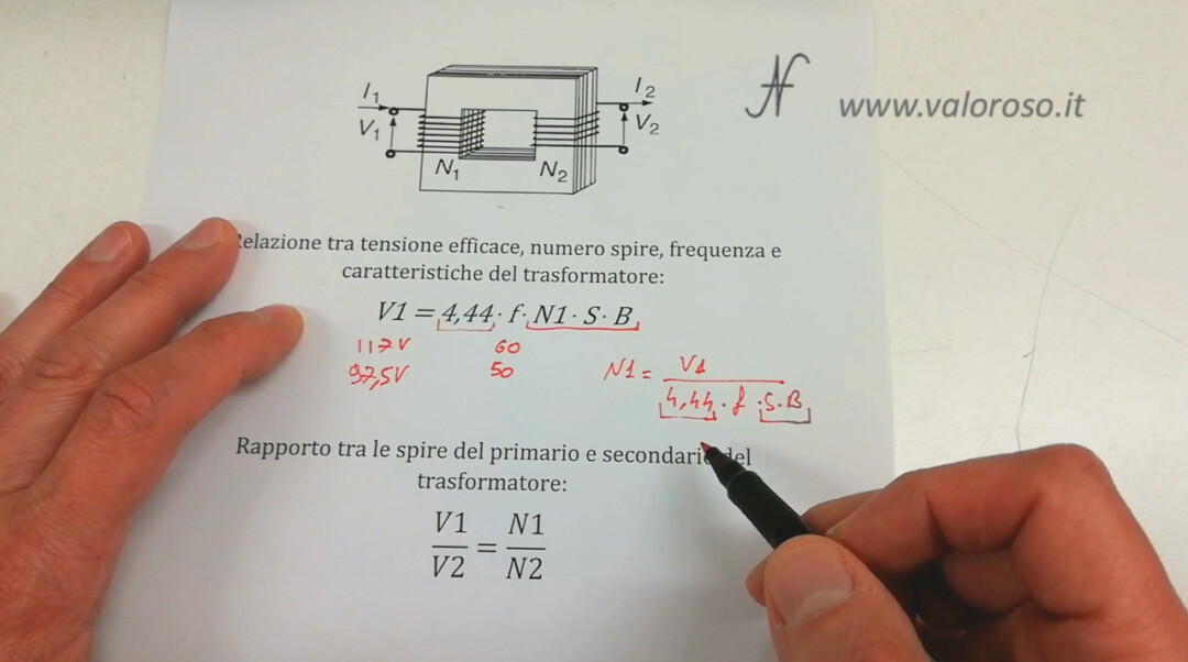
N1 = V1 / (4,44 * f * S * B)
We have already said that S and B they are constant. Suppose we want to keep it constant too V1, the nominal voltage of the primary of the transformer of the Commodore PET.
At this point, we realize that we should increase N1, the number of spire of the primary elected, because, if we reduce the frequency (f) from 60 to 50 Hertz, which is found in the denominator (under the fraction), simultaneously increases the number of turns by 20 percent N1 of the primary winding.
Obviously it's just theory, as we can't physically increase the turns of the Commodore's transformer.
Keeping the Commodore transformer supply voltage lower, then from 117 V to 105 V coming out of the Bronson++ VT-300, obviously it will also lower the voltage at the secondary of the transformer a little (V2), because the relationship between the coils N1 / n2 of the primary and secondary is constant (we are not going to modify the PET transformer).
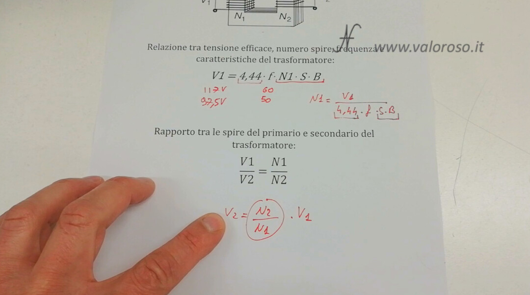
V2 = (N2/N1) * V1
Hence, lowering V1 (the voltage of the transformer primary), it also lowers V2 (the voltage of the secondaries).
We have two possibilities:
- if we keep the primary voltage of the PET transformer at 117V, when this is not designed to do so, because the mains frequency is at 50Hz against 60Hz, the transformer could heat up;
- by lowering the voltage at the primary winding too much, we will also have a lowering of the voltages at the secondary windings, which may not be sufficient for the PET voltage regulators.
With the Bronson ++ VT-300 bought on Amazon, we place the more or less half input voltage between these two situations. We try to minimize the thermal effect on the transformer of the Commodore, keeping the tension lower V1, but we try not to lower it too much V2.
Electrical patterns of the Pet Commodore power supply, CBM 8032
How does this affect the Commodore PET?
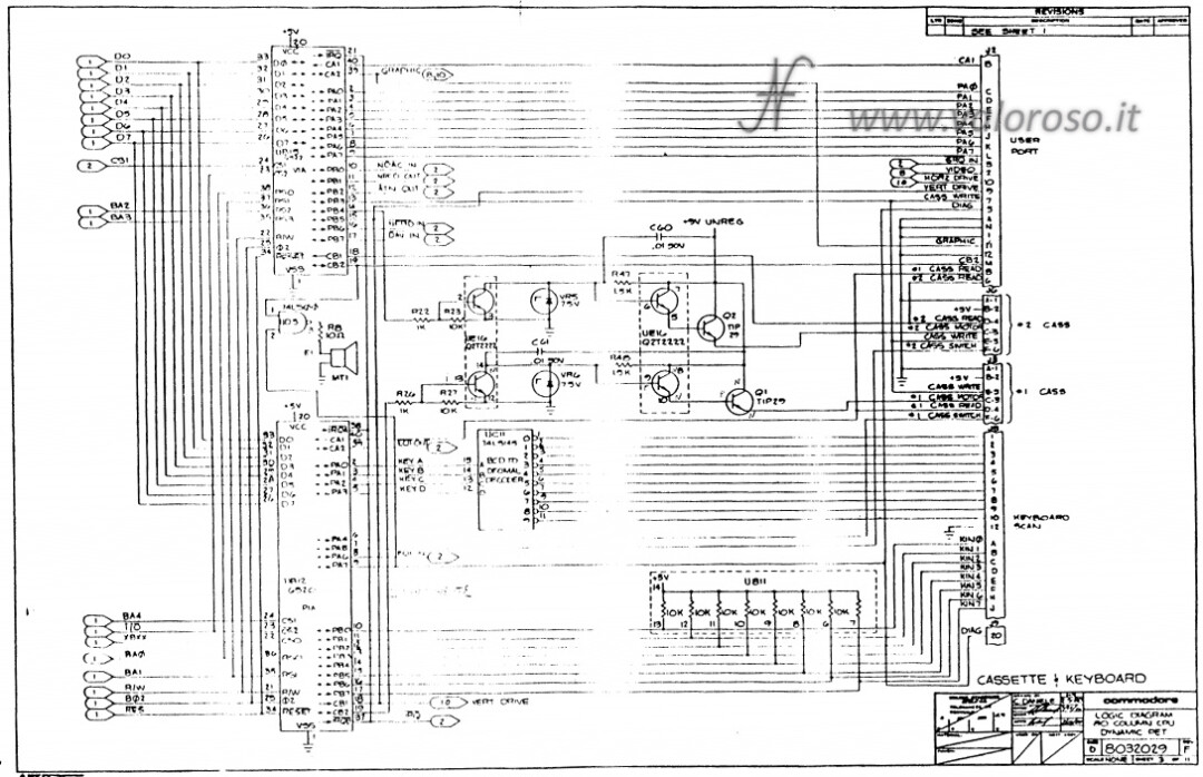
Let's analyze the electrical scheme of the commodore Pet power supply.
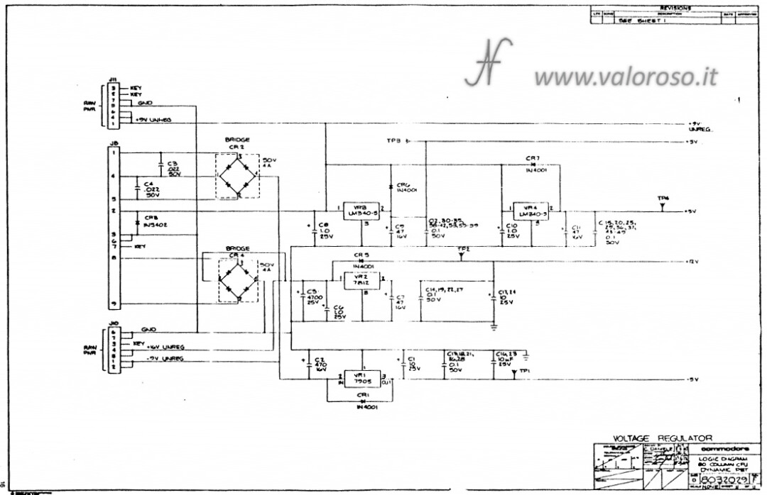
The secondaries of the PET transformer go to rectifier bridges and the AC voltage is rectified and smoothed by the capacitors. At this point, after it has been straightened and smoothed, the voltage no longer has the frequency: neither 50 Hertz nor 60 Hertz. It has frequency 0, since it is a direct voltage!
Subsequently, the rectified and smoothed voltage goes to the various voltage stabilizers: LM340-5, 7812, 7905, which regulate the various direct voltages (5V, 12V and -5V) necessary for the functioning of the motherboard of the CBM 8032.
From the scheme, I do not see a criticality by lowering the frequency from 60 to 50 Hertz because nowhere is this frequency. At the limit, keeping the voltage at the entrance of the regulators a little lower, it is possible that the voltage is too low than the necessary one. However, later, when we feed the PET, we will check that the regulated voltages are actually the correct ones.
There is another socket to the secondary of the transformer, which is the one that goes to the CRT PCB.
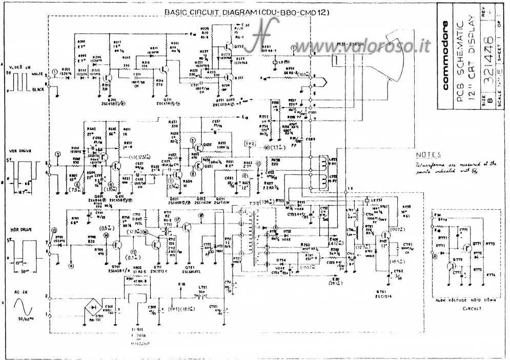
The alternating supply voltage enters the point indicated at the bottom left of the electrical scheme of the CBM 8032. You see that there is precisely written: 50/60 Hertz which means the tab is prepared for both frequencies. In fact, it is true, because the tension is straightened, level and regulated, as we have seen previously.
That said, I feel pretty confident that my Commodore PET will work by the time I feed it with a voltage of 50 Hertz, rather than 60 Hertz.
Connect the Commodore PET, CBM 8032, to the power supply
To test the Commodore PET, CBM8032, we can proceed to make the electrical connections. The power plug of the computer must be connected to the front 110V socket of the Bronson++ VT-300.
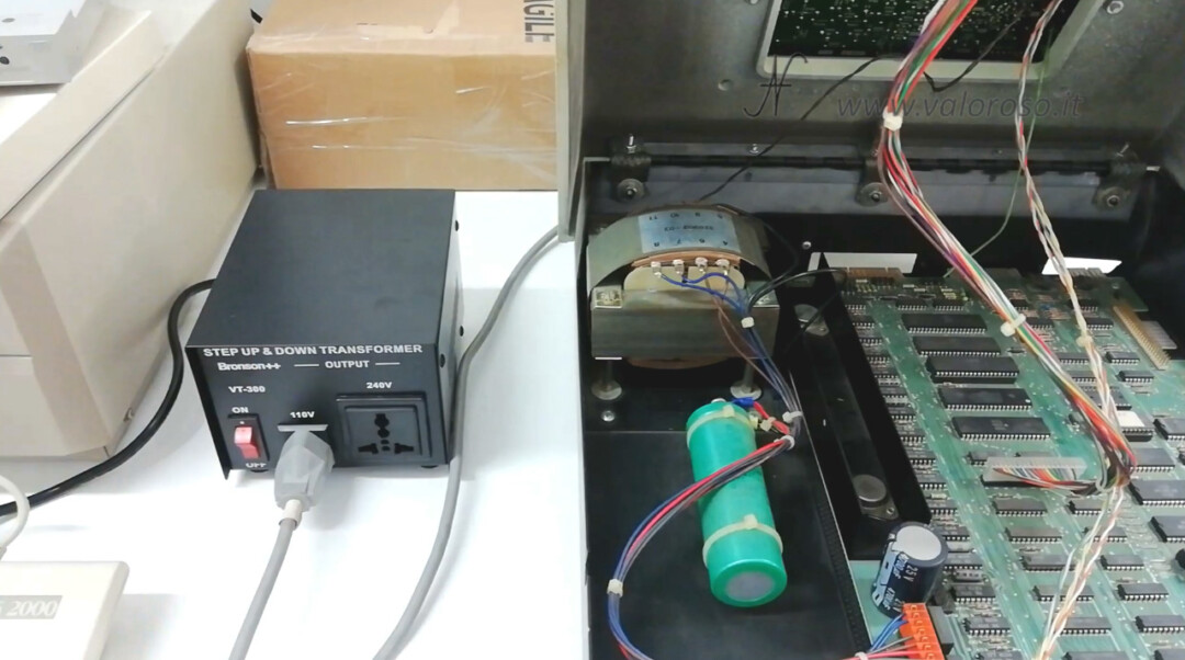
The bronons ++ VT-300 rear power supply is connected to the electricity socket 220V 50Hz.
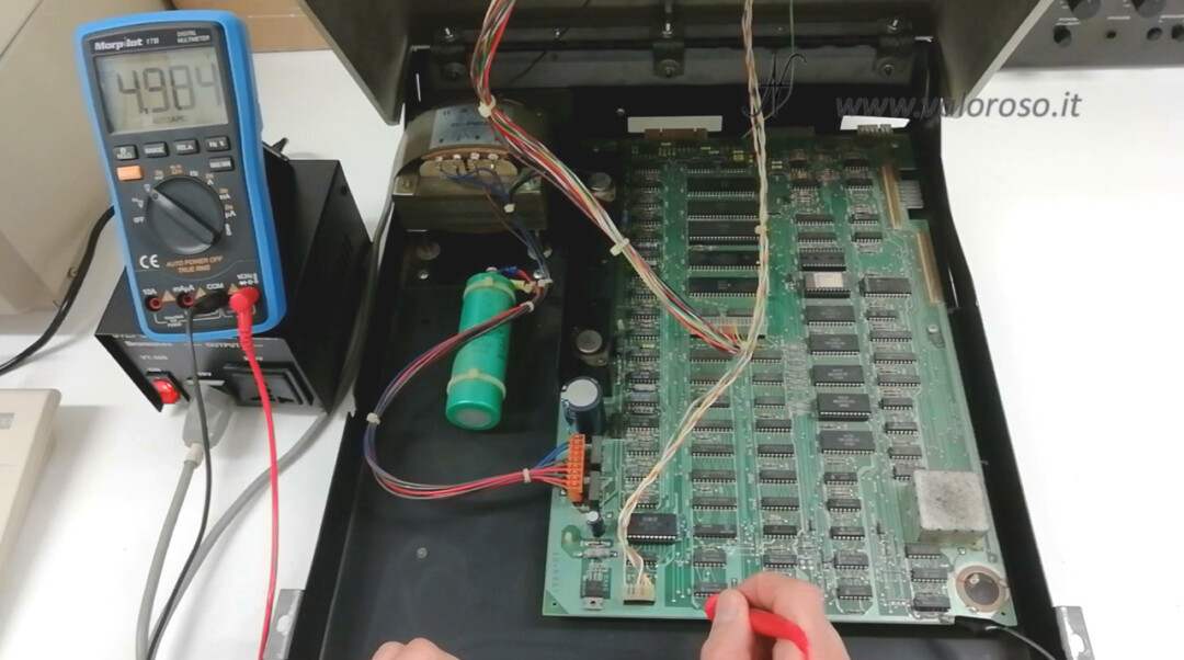
For the sake of consideration, we also open the computer, to measure, with the tester, the various DC voltages after we have turned it on. We have seen in the previous article how to open the Commodore PET, CBM8032.
We light up?
The rear switch of our Commodore PET CBM8032 and already positioned on Hon. The Bronson ++ VT-300 must also be turned on.
It is hours to feed the Commodore PET, CBM 8032
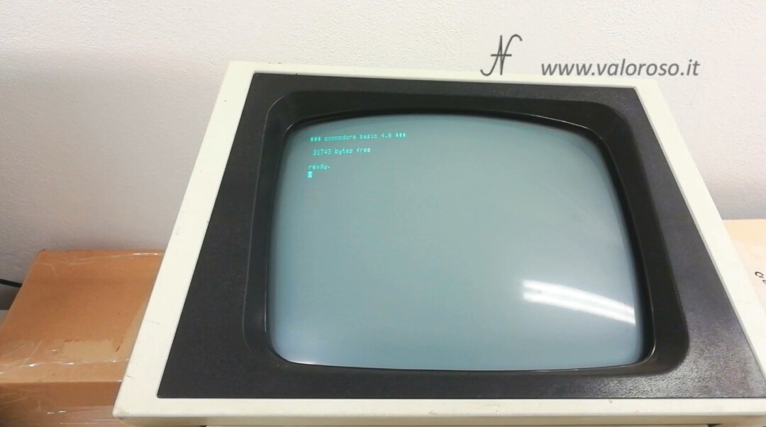
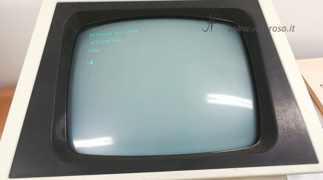
The Commodore Pet, CBM 8032 emits the classic sound at startup! And that's left!
The power supply voltage is correct. The tester is connected to the 5 volts, which one of the most critical voltages within a computer: it must be correctly adjusted because, if it is too high, it burn all the integrated circuits.
The monitor shows some writing! Fantastic!
Better to turn off the computer immediately: you have to give time to the capacitors to regenerate. After a long time that a computer (but also a stereo system, a radio, etc ...) remains off, the capacitors need a little tension, but also a little rest! I explain it in this article.
After a few minutes of rest, we can turn the computer back on and try all the other power supply voltages: 5V, -5V and 12V again.
We can also note that the transformer does not heat: it is cold.
The Commodore PET test, CBM 8032
Here, the first thing I notice is that the writing Commodore Basic 4.0 wobbles a little. I will have to inquire if it is normal or if it is a defect to be investigated. It is as if it moves left and right by a millimeter.
Also, the vendor had already informed me that the keyboard was not working properly.
Not even a button goes!
I would like to make sure the keyboard problem is not related to the motherboard. Let's see the wiring diagram.
The keyboard is managed in a similar way to that of the Commodore 64. It is scanned in rows and columns, through the integrated MOS 6520 circuit, otherwise known as PIA.
Let's do a test with a piece of electric wire. On the keyboard connector, we try to simulate the pressure of a few keys, joining, through the electric wire, a few lines with a few columns.
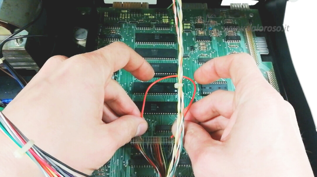
A monitor ... something is written! The seller was right, it is the keyboard not to work.
Continues ...
Soon, we will have to disassemble the keyboard is to see what's there that does not make contact, on any key. It amazes me that no key to the keyboard works. So, either all the rubbers who press on the printed circuit board have been dried, or there is oxide. But this is only the future will tell us.
To be notified when I publish more videos related to retro computers and vintage electronics, I invite you to subscribe to the YouTube channel and activate the notification bell!