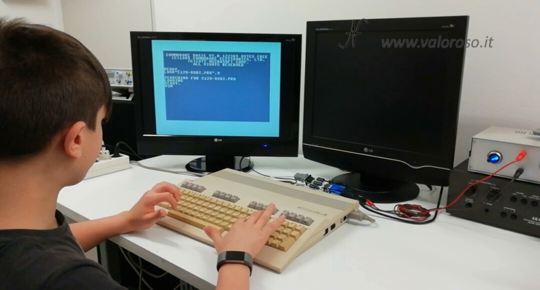
In today's video, let's see how to connect two color monitors to the Commodore 128using the output Rgbi, in addition to the video exit. The Commodore 128 is in fact equipped with a second graphic chip, the VDC, whose signals come out on the RGBI rear door.

The RGBi port can be connected to an RGBI or CGA color monitor, plus it has a pin with a black and white composite video signal.
RGBI (CGA) to VGA 15kHz adapter, mounting
The first step in connecting two color monitors to the Commodore 128 is to build an adapter to connect the RGBI port to a VGA color monitor (which supports 15KHz signals). Ivan Sergio created the printed circuit on the basis of Travis Durf's scheme, available on the net and shown below.
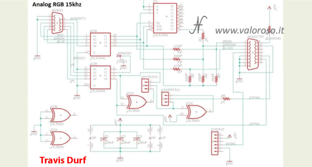
The adapter is not compatible with all VGA monitors. It is necessary that the monitor supports the horizontal sync frequency of 15KHz, instead of the standard ones, which start at 31KHz.
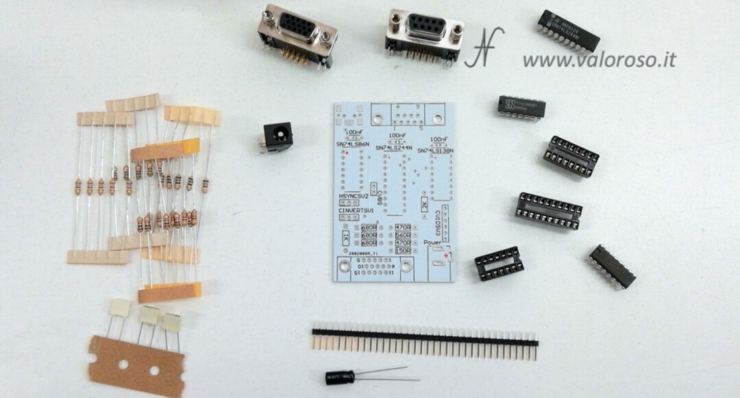
We begin to mount the resistors, which are the lowest components. A little at a time, we insert them in their correct position, mounting them adhering to the printed circuit. Finally we cut off the surplus of the leads.

I had made a tin soldering tutorial, whoever is interested can find it by following this connection.
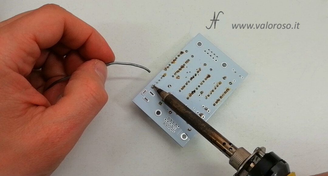
We continue the assembly of the printed circuit with the sockets of the integrated circuits. We begin to weld 2 pawns for each plinth, at opposite corners, so that we can straighten the plinth by heating the two feet just soldered. Be careful to insert them in the correct direction, identified by a notch. When the sockets are straight, we can solder the other feet.
Let's move on to the 100nF filter capacitors. We solder them straight and adherent to the printed circuit board. Then we cut off the surplus of the leads.
It is the turn of the pin strips. One at a time, to mount it straight and adherent to the printed matter, we begin to weld only one pin. Then we straighten it and finally we weld the other feet.

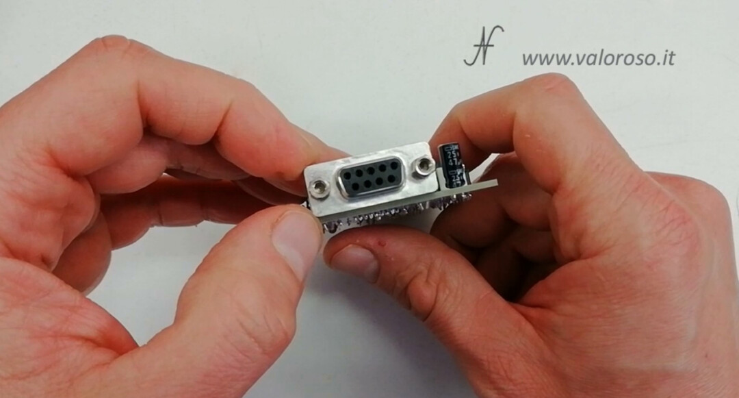
We mount the two connectors, the 9-pin and the 15-pin one. In addition to the feet, we also weld the side supports, which serve to strengthen the installation.
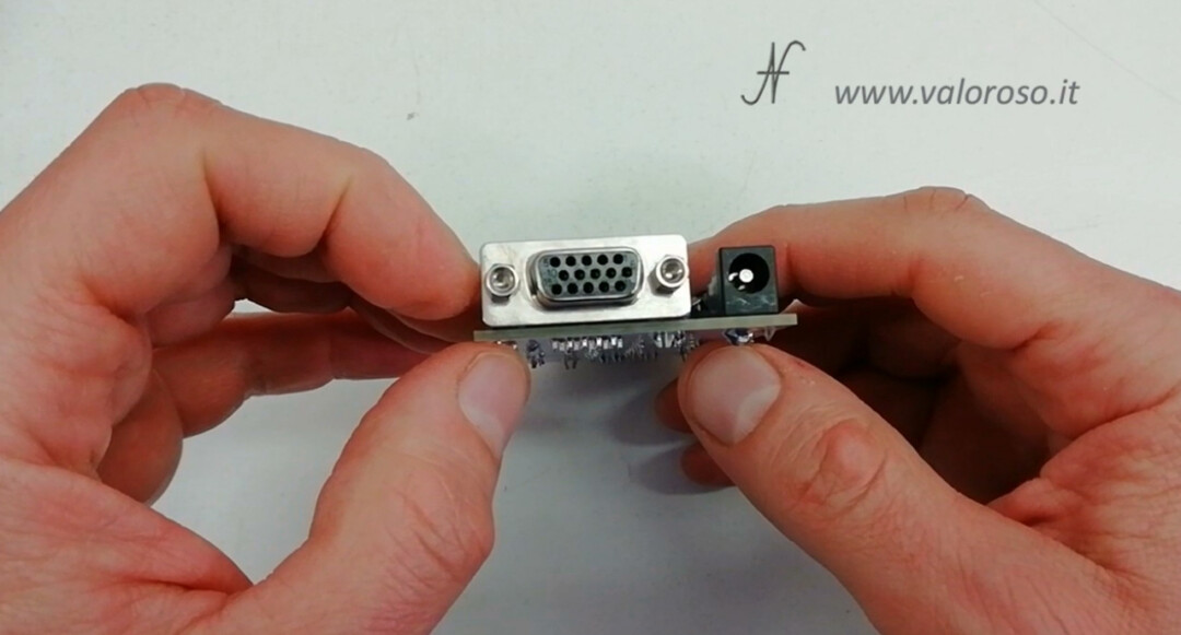
We also solder the power connector. The adapter needs an external 5V power source.
To complete, I wanted to add an electrolytic capacitor on the 5V power line, as an additional filter.
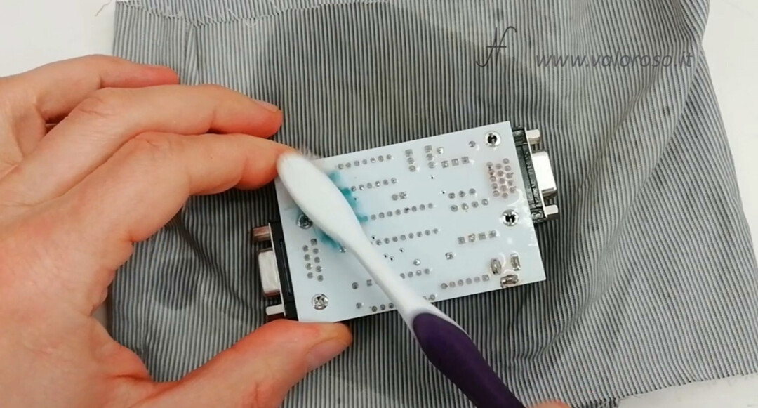
After having welded all the components, we can clean the printed with a toothbrush, a cloth that does not leave lint and alcohol.
We then mount the three integrated circuits on their respective sockets, paying attention to the correct direction.
Since, with the connector that I bought, the power supply voltage did not pass on the predisposed pin, I had to mount a jumper. Details of the jumper can be found in the video.
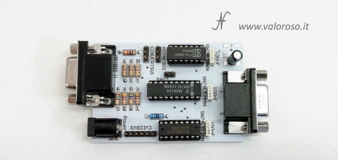
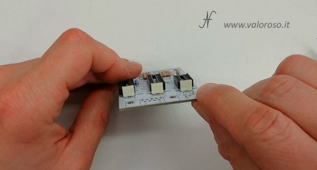
At this point we can mount the jumpers on the CINVERTSV1 and HSYNCSC2 connectors. Although I have not found any differences by reversing the polarity of the pulses, I suggest starting to mount the jumpers in the position indicated in the photo.
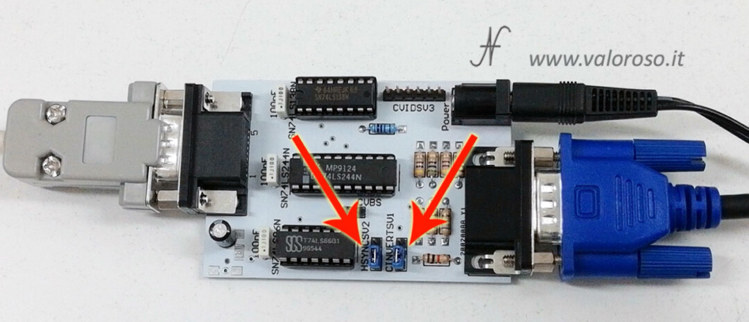
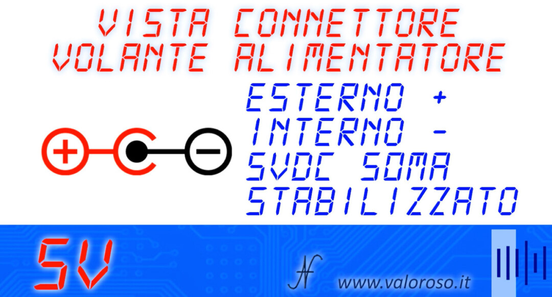
Before powering up, I suggest testing any short circuits on the power supply line with the tester. With regard to the polarity of the 5V power connector, the positive is located outside the connector, while the central pin is the negative. The converter to connect two monitors to the Commodore 128 consumes about 50mA.
Connect two monitors to the Commodore 128, cables
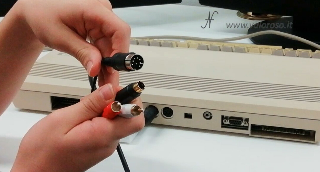
Let's start connecting the SVideo cable for the number one monitor signals. The SVideo cable starts from the 8-pole DIN Video connector behind the Commodore 128 and arrives behind the TV. A composite video cable with a 5-pin DIN connector can also be used instead of the S-Video cable.
We connect the cable with two male -mastery DB9 tractors between the Commodore 128 and the RGBI adapter (CGA) - VGA. Beware of the footing! It is not possible to mount a connector on the adapter to put it directly in the RGBI gate. The arrangement of the feet is not mirror, but is pin to pin.
We also connect the VGA cable between the adapter and the second monitor.
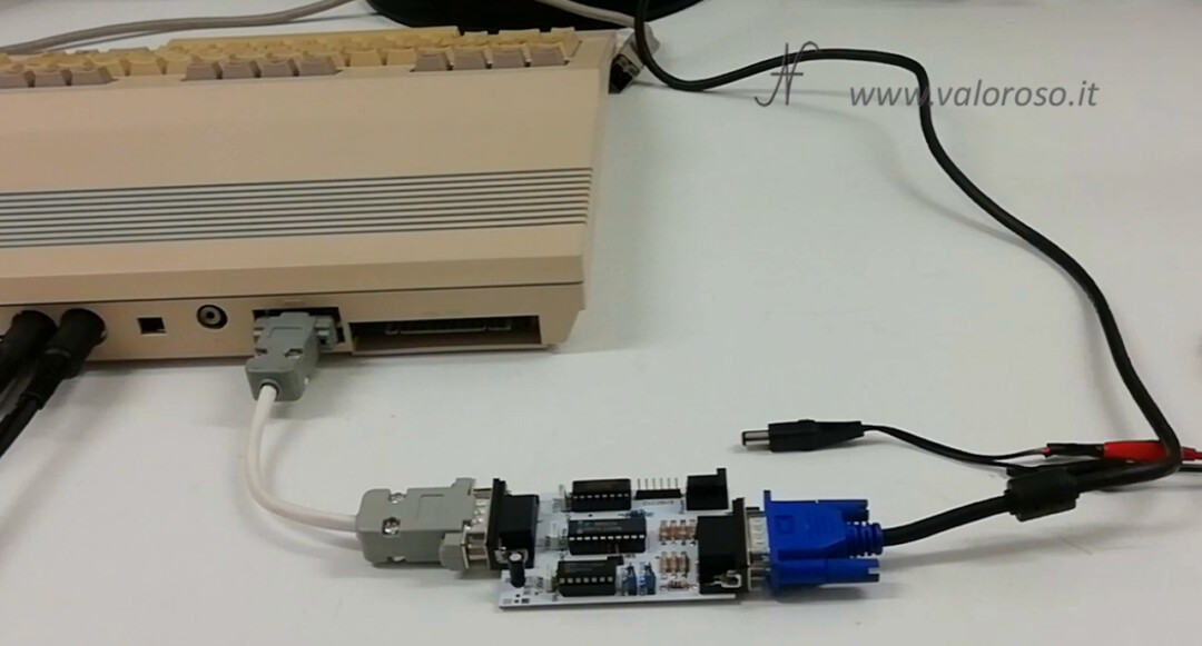
Finally, we connect the external 5 Volt power supply, which must deliver a current greater than that absorbed by the converter, which is about 50mA.
Connect two monitors to the Commodore 128, the Basic test program
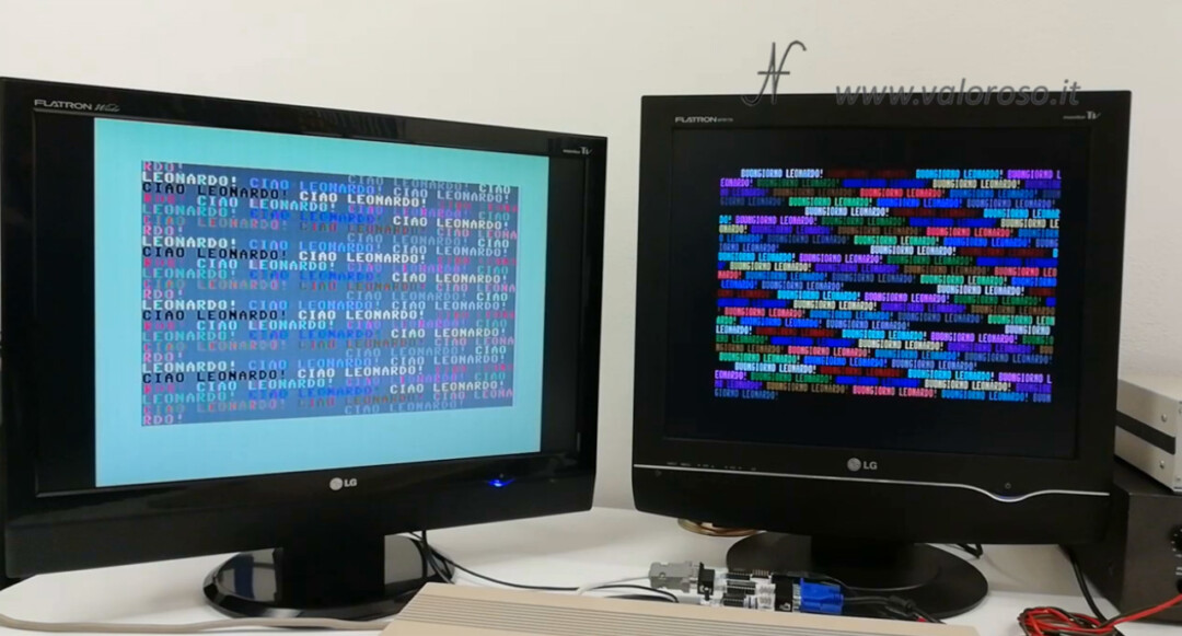
After turning everything on, let's load the example program, which you can find at the bottom of this page. On each monitor are displayed different writings, in color.
Dopo aver digitato il proprio nome, il primo monitor visualizza "CIAO", seguito dal nome, con diversi colori. Il secondo monitor visualizza "BUONGIORNO", seguito dal nome.
Come scrivevo prima, non tutti i monitor VGA supportano segnali con sincronismo orizzontale a 15KHz. In rete si trovano degli elenchi di monitor compatibili. Collegando un monitor non compatibile, l’immagine non si formerà del tutto o sarà incomprensibile. E’ possibile anche che il monitor dia un messaggio di errore tipo "OUT OF RANGE", "FUORI CAMPO" o similare.
Basic commands to use two monitors with the Commodore 128
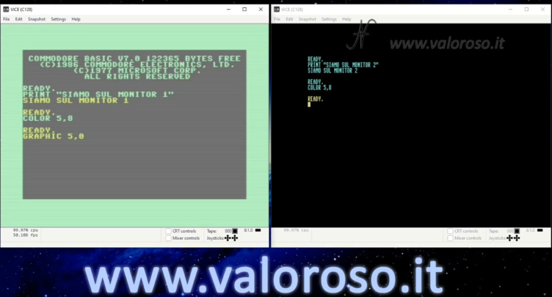
To learn more, let's see the commands in Basic with the VICE emulator for using two monitors with the Commodore 128. As soon as it is turned on, if the 40/80 column button is not pressed (40/80 display), the Commodore 128 is positioned on monitor 1, the standard 40 column one. We can also change the color of the writing using the command:
COLOR 5,numero_del_colore
To switch to the second monitor, connected to the RGBI port, use the command:
GRAPHIC 5,0
Also on the second monitor you can change the color of the writing, using the same command COLOR just seen. To return to monitor 1, use the command:
GRAPHIC 0,0
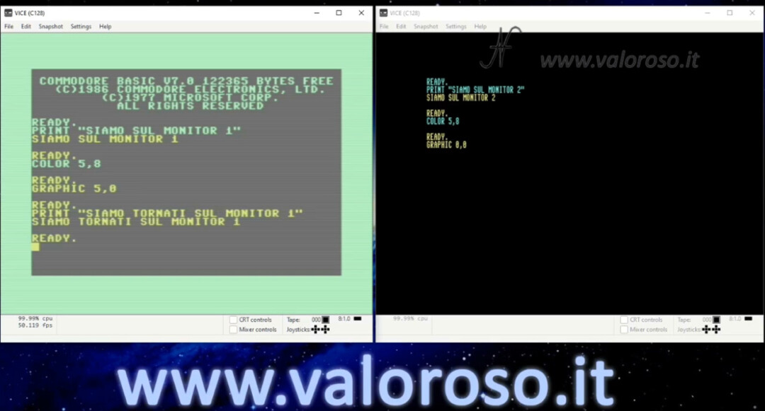
The example program found at the bottom of the page is based on this principle.
Basic example program to manage the double monitor on the C128
Commodore-128-dual-monitor.zip, to be expanded, inside there is the basic program in PRG and D64 format.
Credits: In the video tutorial, SID music is ACE II by Rob Hubbard.
To be notified when I publish more tutorials, experiments and reviews related to retro computers and vintage electronics, I invite you to subscribe to the YouTube channel and activate the notification bell!
Hello, all beautiful and explained very well, but I would like to ask you a couple of questions ... the first is where Ivan Sergio's printed circuit is available, the second is which model you used for viewing 80 columns. I see that it is an LG but I can't understand what the precise model is.
Thank you...
Hello! Thank you. For the printed circuit board, you can contact Ivan Sergio directly on Facebook. If you can't, let me know that I'll put you in touch. Regarding the LG monitor, the model is this: Flatron M1917A.
Amedeo, the topic of this video of yours was really interesting, above all because it explains after many years that the Commodore with the 128 was innovative but that unfortunately as you well know you too did not have many consents, when this mode of using two motiro connected to the computer, is now widely used for desktop publicising, video editing, for creating sites and for 3D modeling in the industrial area. Don't you find?
Amedeo, dopo aver seguito il link di retrofixer, suggerito da te in una risposta, a non so quale tuo video, mi ha incuriosito, ripeto un video di retrofixer, sulla realizzazione di una cartuccia generica per la diagnostica e il dead test per il C64, con l'uso di EEPROM, e di un programmatore "Minipro", nella fattispecie un TL866II della XGECU.
Now, Retrofixer, has also mounted a display with voltmeter function, not hoof, on the PCB, but steering wheel. If you will be able to see the video too. Trivial question, but what is the use of us already mounting in memory of EEPROM, the software for diagniostica?
Of course, I agree. I myself use multi monitor computer to work.
I have to find the video you're talking about. The diagnostic software may reside inside the EEPROM, alternatively, if the computer starts, you can load the diagnostic software from other media. There are various types of software for different diagnostic needs.